PG-FP5 CHAPTER 7 USAGE THE REMOTE CONNECTOR
R20UT0008EJ0400 Rev. 4.00 Page 133 of 240
Jul 15, 2010
CHAPTER 7 USAGE THE REMOTE CONNECTOR
This chapter describes the use of the remote connector.
The FP5 can be remote controlled by connecting the remote connector and external control device. Remote control
can be used to operate and check writing and PASS/ERROR displays from the external control device.
7.1 Remote Interface Mode
The remote interface has a standard mode and a bank mode.
The modes are switched by using the FP5 Manager [Enable Bank mode] check box.
Standard mode: The same signals as the control buttons (NEXT, ENTER, CANCEL) on the command menu of the FP5
unit can be input.
Bank mode: This mode allows inputting of the bank signals (BANK0-2) that indicate the programming area. The
control buttons (NEXT, ENTER, CANCEL) will change their functions to those inputting bank signals,
so that the command menu displayed on the FP5 message display will be disabled.
7.2 Remote Connector Pins
The FP5 remote connector pins have the following functions. All inputs will become active with an effective level of 50
ms or greater. Note that the pin numbers in Table 7-1 are the pin numbers on the FP5 remote connector.
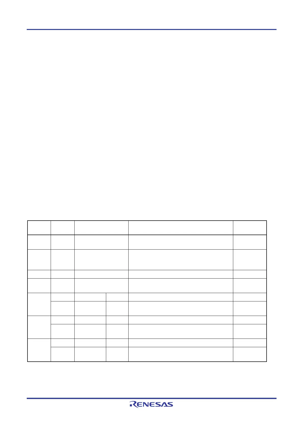
Table 7-1. Remote Interface Pin Functions (1/2)
Pin
number
Input/
Output
Pin name Function Active level
1 Output CONN Indicates that the remote interface is connected. When
the FP5 power is ON, the CONN is always valid.
High level
2 Output BUSY Outputs the status indicated by the status LED “BUSY”.
Note that the BUSY signal differs from the status LED
and does not blink.
High level
3 Output PASS Outputs the status indicated by the status LED “PASS”. High level
4 Output ERROR Outputs the status indicated by the status LED
“ERROR”.
High level
Input Standard mode CANCEL Same as the CANCEL button function. Low level 5
Input Bank mode BANK0 Indicates the lowest 1 bit of the 3-bit programming area
number.
Low level
Input Standard mode ENTER Same function as the ENTER button. Low level 6
Input Bank mode BANK1 Indicates the middle 1 bit of the 3-bit programming area
number.
Low level
Input Standard mode NEXT Same as the function of the NEXT button. Low level 7
Input Bank mode BANK2 Indicates the highest 1 bit of the 3-bit programming area
number.
Low level