PG-FP5 CHAPTER 2 HARDWARE CONFIGURATION
R20UT0008EJ0400 Rev. 4.00 Page 23 of 240
Jul 15, 2010
message display functions will change. Refer to 4.3.2 (9) [FP5 Manager] Command and CHAPTER 7
USAGE THE REMOTE CONNECTOR.
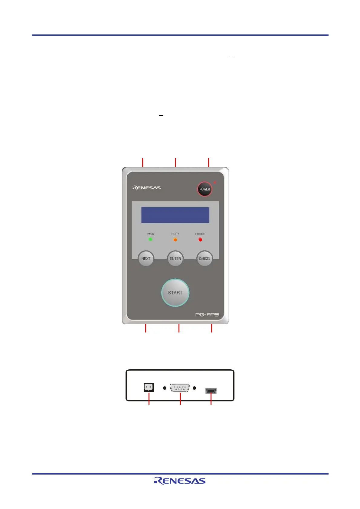
2.3.2 FP5 connectors
The power supply connector, serial connector and USB connector are laid out on the host interface side.
The target connector, GND connector and remote connector are laid out on the target connector side.
When the FP5 Manager is used to switch to the bank mode or simple mode, the button functions and message display
functions will change. Refer to 4.3.2 (9) [FP5 M
anager] Command and CHAPTER 7 USAGE THE REMOTE
CONNECTOR.
Figure 2-3. FP5 Top View <Connector>
Figure 2-4. FP5 Host Interface Side
USB connector Serial connector Power supply connector
Target connector
GND connector
Remote connector
Power supply connector
USB connector
Serial connector