PG-FP5 CHAPTER 4 PROGRAMMING GUI USAGE
R20UT0008EJ0400 Rev. 4.00 Page 41 of 240
Jul 15, 2010
CHAPTER 4 PROGRAMMING GUI USAGE
This chapter explains functional details on windows and dialog boxes of the programming GUI.
4.1 Introduction
Make sure that the programming GUI, USB driver, and the FP5 parameter file (PR5 file) for the target device are
installed. For the installation method, refer to CHAPTER 3 SOFTWARE INSTALLATION.
4.2 Startup of Programming GUI
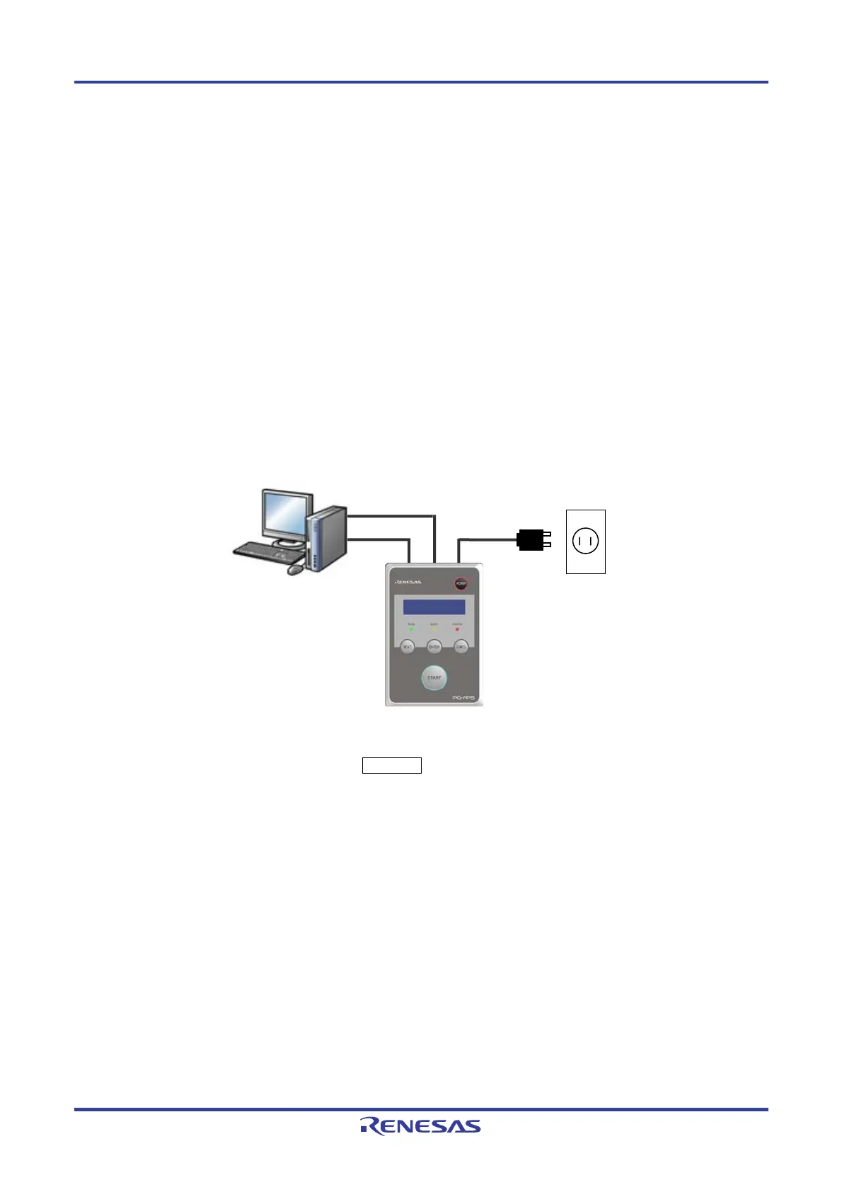
(1) System connection
Connect a USB cable (or serial cable) to the USB port (or serial port) on the host machine, and the other side of the
cable to the USB connector (or serial connector) on the FP5. Plug in the AC adapter and then connect to the FP5
power supply connector.
Figure 4-1. System Connection
(2) FP5 startup
After the cables are connected, press the POWER button on the FP5. When the FP5 is correctly started, the
POWER LED is turned on and “Commands >” is displayed in the message display. If not, the cause may be a
defect in the FP5, so consult a Renesas Electronics sales representative or distributor.
Serial cable
AC adapter
USB cable
Host
machine
FP5
or
Outlet