PG-FP5 CHAPTER 7 USAGE THE REMOTE CONNECTOR
R20UT0008EJ0400 Rev. 4.00 Page 134 of 240
Jul 15, 2010
Table 7-1. Remote Interface Pin Functions (2/2)
Pin
number
Input/
Output
Pin name Function Active level
8 Input VRF Inputs the independent verify signal. Low level
9 Input START Inputs the “START” (Auto-procedure (E.P.)) signal. Low level
10 Input CLR Clears (disables) the “PASS” and “ERROR” signals. Low level
11 to 15
−
GND Grounding pin
−
Table 7-2. Programming Area and Banks
BANK2 BANK1 BANK0
Programming area 0 0 0 0
Programming area 1 0 0 1
Programming area 2 0 1 0
Programming area 3 0 1 1
Programming area 4 1 0 0
Programming area 5 1 0 1
Programming area 6 1 1 0
Programming area 7 1 1 1
Remarks 1. 0: Low level
1: High level
2. When set in programming area 0, set in programming area 0, set BANK0, BANK1, and BANK2 to the low
level.
When set in programming area 3, set BANK0 and BANK1 to the high level, and BANK2 to the low level.
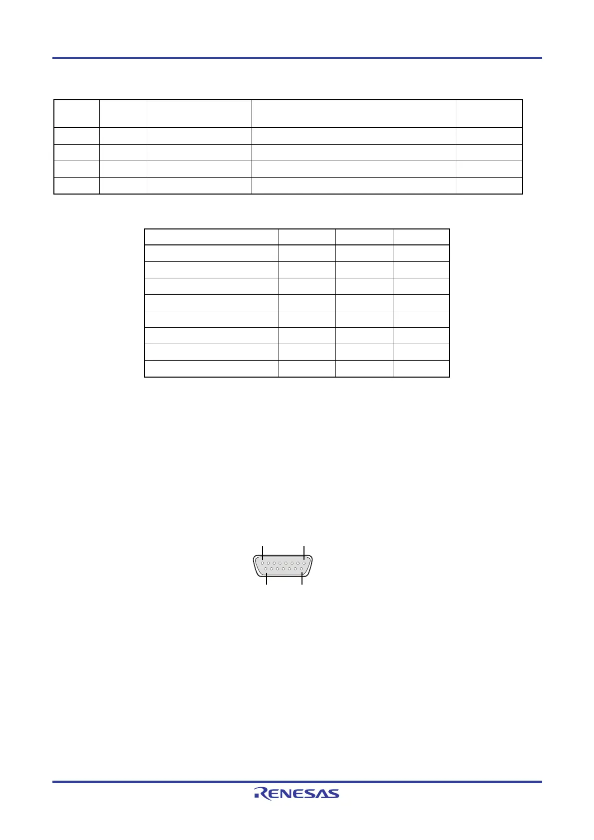
Next, the pin assignment of the remote connector is shown.
Figure 7-1. Remote Connector (D-SUB 15 pin connector (female)) Pin Assignment
Remark Remote connector (D-SUB 15 pin connector (female)) model number: 07433FB015S200ZU (Suyin
Connector)
8
15
9