Secon 7
Integra 3™ Temperature Control
Research Instruments Ltd
7
INTEGRA 3
13/06/13
REV
ASSEMBLY
DESIGN
DATE
DIMENSIONS IN mm
DRAWN BY
DATE
MATERIAL
TRACEABILITY
FINISH
SCALE
PRODUCT
TITLE
DRAWING
NUMBER
2:3
Probe in nozzle
DSS
PURCHASING
SIGNATURES
THIRD ANGLE
PROJECTION
P2
INTEGRA 3 WITH THERMOSAFE (COMMON)
ECN
SHEET
1
2
3
5
6
7
8
4
A
A
B
B
C
C
D
D
E
E
F
F
TOLERANCES
(UNLESS
OTHERWISE
STATED)
X
0.5
X.X
0.1
X.XX
0.05
RESEARCH INSTRUMENTS LTD
GEOMETRIC
0.05
NO
BATCH
SERIAL
1 OF 1
--
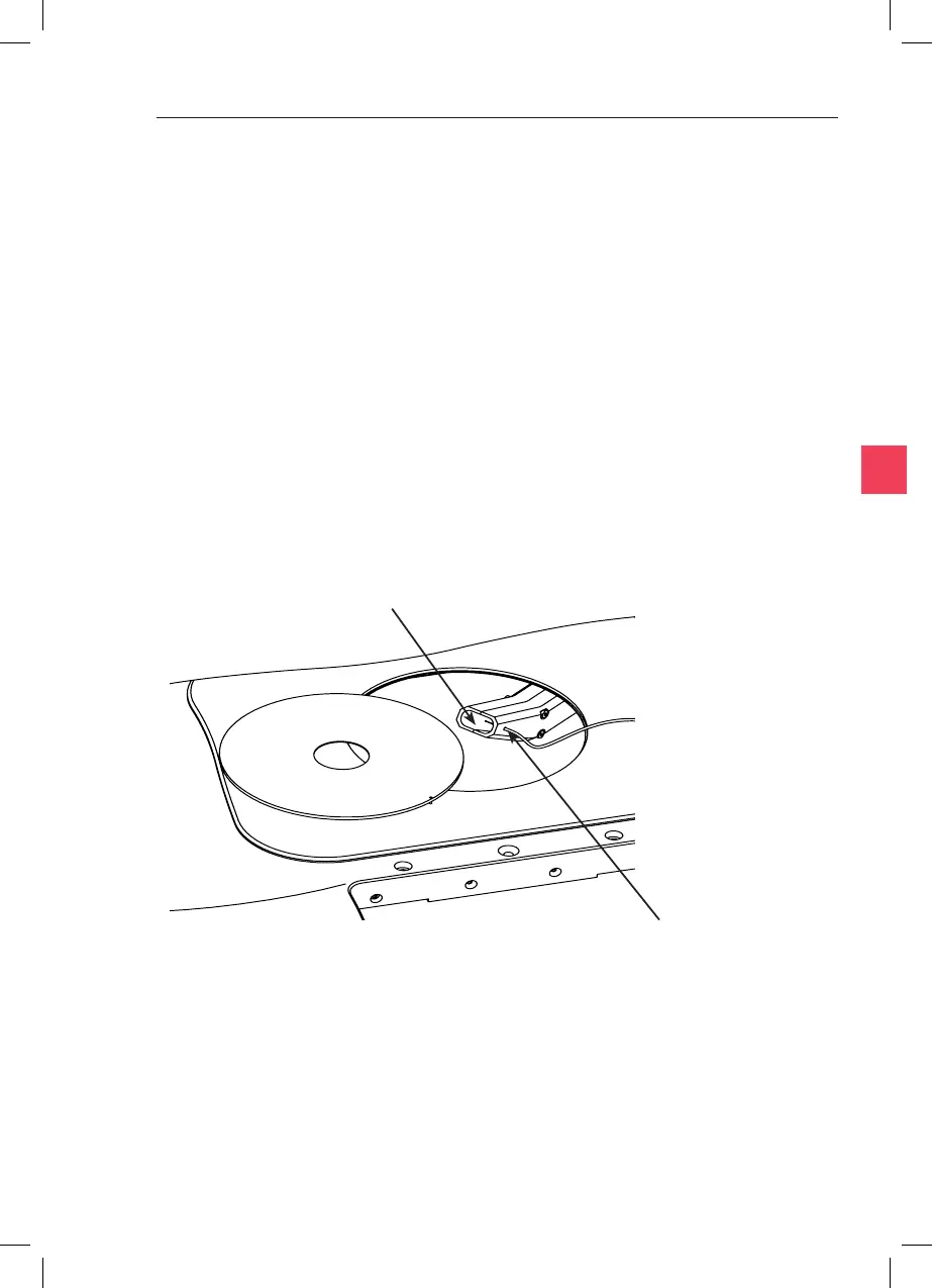
Pass thermocouple probe through this hole
Posion thermocouple probe p in the centre of the nozzle
Figure 7-4
For the Heated Glass Insert, it is not recommended that
temperatures are measured directly above the objecve during
calibraon. This is because the objecve cools that part of the plate.
Either move the objecve away from the glass or measure slightly to the
side of the objecve as shown (Figure 7-3).
Access to the air nozzle from above will be improved by liing out the
Metal Heated Insert and moving to one side.
Place the probe of a calibrated thermometer through the small hole on
the side of the air nozzle (see Figure 7-4) unl the probe p is centralised
in the air stream.
Aer switching on, wait at least 20 minutes to allow the temperature
to stabilise before calibrang.