Rexroth IndraDrive C Electrical Data 6-37
DOK-INDRV*-HCS02.1****-PR02-EN-P
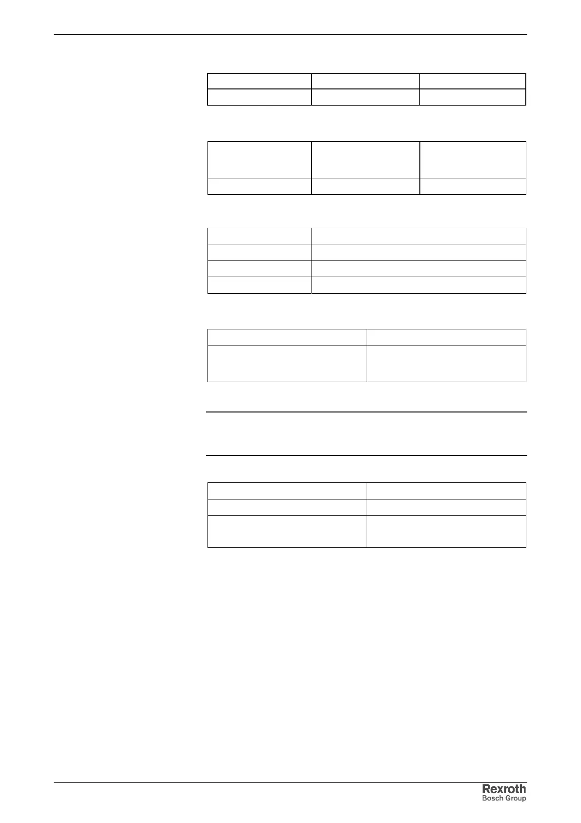
Type Number of poles Type of design
Spring power 4 Pins on connector
Fig. 6-46: Design
Cross section
single-wire
[mm²]
Cross section
multi-wire
[mm²]
Cross section
in AWG
0.14-1.5 0.14-1.5 28-16
Fig. 6-47: Connection Cross Section
4 +24 V
3 +24 V
20 V
10 V
Fig. 6-48: Identification of the individual connections
looping through the power supply up to max. 6 Aeff allowed
polarity reversal protection over the allowed voltage range by
internal protective diode of +24V
circuit
Fig. 6-49: Load capacity
Note: The input 0 V connected in conductive form with the housing
potential. It is therefore impossible to use an insulation monitor
at +24 V and 0 V against housing.
line cross section min. 1 mm²
line routing preferably in parallel
max. allowed inductance between 24V
supply source and X13
100 µH
(corresponds to approx. 2*75 m)
Fig. 6-50: Supply line 24 V
Design
Connection Cross Section
Connection
Load Capacity
Lines +24 V and 0 V
 Loading...


