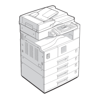
GENERAL LAYOUT
B545 18 SM
4. DETAILED DESCRIPTIONS
4.1 GENERAL LAYOUT
1 Upper junction gate 5 Stapler
2 Punch unit (option) 6 Stapler tray
3 Stapler junction gate 7 Tray 2
4 Pre-stack tray 8 Tray 1
Tray junction gate: Directs paper either to the upper or lower exit. In staple mode,
the stack always goes out to the lower exit.
Stapler junction gate: Directs paper either to the lower exit or to the stapler tray.
Pre-stack tray: When stapling multiple copies (A4 S, LT S, B5 S only) in the staple
mode, the first sheet of the second copy waits here for the next sheet to feed while
the previous stack is stapled. After the second copy is fed, the first and second
sheets are fed together to the pre-stack tray. This delay allows enough time for the
previous stack to be stapled without interrupting paper feed.
Shift trays: Tray 1 (upper) and tray 2 (lower) shift side to side in the sort mode,
and raise and lower to receive ejected copies.
Stapler tray jogger: Employs positioning rollers and jogger fences to align stacks
for stapling.
Punch unit. Punches holes in stacked copies.
B352D118.WMF
1
2
3
4
5
6
7
8