2.3.4 Tracking mechanism
Because a belt photoconductor is used, shifting of the
belt forward and backward cannot be avoided when it is
driven. Correction is also required to minimize stress
and distortion of the belt. Therefore, this machine
employs an offset correction mechanism to minimize
stress and distortion of the belt, and to prevent it from
tilting vertically from its horizontal axis.
The tracking rollers and the eccentric shaft are
assembled with the front and back side plates of the
OPC tracking unit. Because both ends of the shaft are
eccentric, the tracking rollers turn in the vertical direction
with the balancing point of the OPC tracking unit as the
center, every time the eccentric shaft makes a half turn.
This drive is achieved by rotating the eccentric shaft a
half turn via the gears by the tracking motor in the OPC
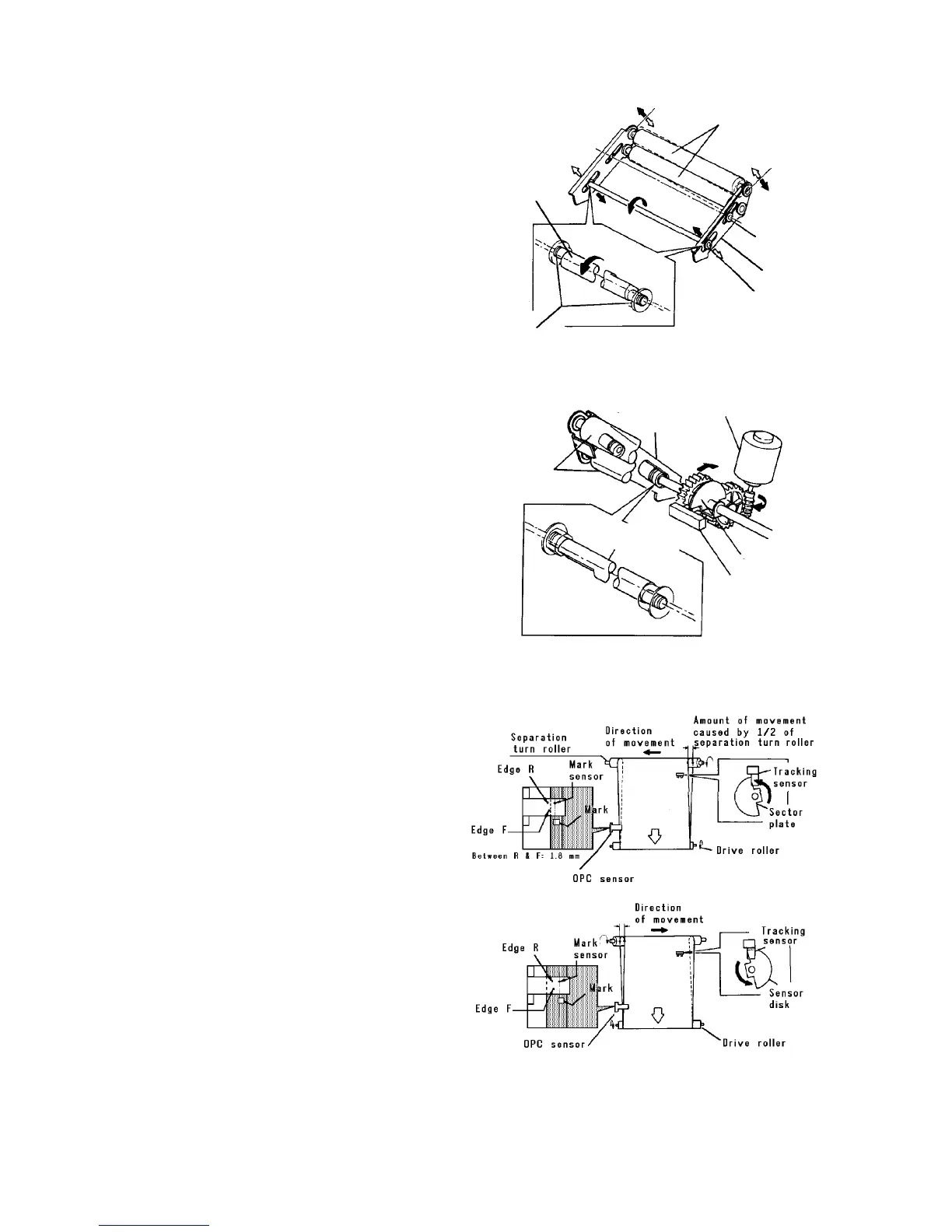
unit. The sector sensor is turned ON/OFF by the sector
disk to output a signal for half rotation. At the same
time, it detects the tilt direction of the separation turn
roller.
The principle of offset correction
The tracking mechanism corrects offset in the OPC belt.
The OPC sensor monitors rear edge of the OPC belt. If it
moves away from the correct position, the OPC sensor
detects it and the tracking rollers positions are changed.
This is repeated and corrects offset in the OPC belt
while the OPC belt is turning.
There are three sets of light emitters and receivers in the
OPC sensor, they are the OPC home mark sensor, front
edge (Edge F) sensor, and rear edge (Edge R) sensor.
The OPC home mark sensor detects the home mark on
the rear of the OPC belt. The other sensors are used to
detect the OPC belt position.
When the OPC belt moves too far to the rear, both the
rear and front edge sensors turn on as the edge of the
OPC belt comes between the light emitters and
receivers. On the other hand, when the OPC belt moves
too far to the front, both of them turn off. At these times,
the tracking rollers are moved to return the belt to the
correct position.
Tracking roller
Tracking unit
balancing point
OPC tracking unit
Eccentric shaft
Bearing
Eccentric shaft
Front
side
plate
Tracking motor
Sector disk
Tracking sector
sensor
Eccentric shaft
Separation
turn roller