2.9 Development
2.9.1 Main construction
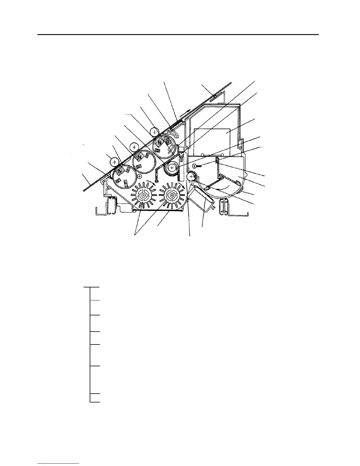
Structural diagram
Construction
Three magnetic rollers are used to meet the high speed
requirements.
Two paddle wheels, a separator, and a transport auger
are used for agitation.
Negative bias voltage is applied to the development
rollers.
The toner density sensor controls the toner density. The
control condition is changed by data from the ID sensor.
The toner density sensor detects toner end condition.
The toner near-end sensor is also used to detect the
near-end condition.
There are two detecting mechanisms for the toner
cartridge replacement. One is to detect the set of the
cartridge. The other is to detect the shutter operation of
the cartridge.
An independent dc motor drives the unit.
A blower sends air to the ID sensor to prevent the
sensor from becoming dirty.
Separator
Toner density sensor
Toner cartridge
Developer auger
Small toner agitator
Main toner agitator
Toner hopper
Toner near-end sensor
Toner supply roller
Toner density control board
Toner inlet
Development unit
shutter
Paddle wheel
Development backup roller
1st development roller
2nd development roller
Backspill plate
ID sensor
Filter
Developer inlet
Opening
3rd development roller
Doctor blade
OPC belt
Development unit Development mechanism
Developer agitator mechanism
Development bias mechanism
Toner density control and supply
mechanism
Toner near-end detection
mechanism
Toner cartridge replacement
Drive mechanism
ID sensor anti-contamination
mechanism