2.1.3 Replacing parts in the paper trays
PM cycle: Lubricate the tray motor worm
gear every 800K
1. Pull out the tray.
2. Remove the front and rear knobs (2 screws each),
and the tray bottom plate (6 screws). You can
replace the anti-condensation heater and paper
size sensors.
3. Remove the front tray cover (4 screws). You can
replace the front tray drive wire.
4. Remove the paper tray from the rails (2 screws)
when:
• Replacing the rear tray drive wire
• Replacing the tray motor and DC drive board
• Lubricating the worm gear
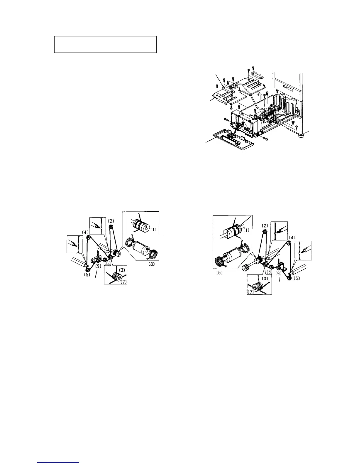
Tray drive wire layout diagram
The numbers shows the assembly steps.
Knob
Tray bottom
plate
Front tray cover
FRONT REAR
Secure the
tension pulley
2 turns counter-
clockwise (blue wire)
2.5 turns counter-
clockwise
2.5 turns
clockwise
Secure the tension
pulley
2 turns
clockwise
(blue wire)