Electrical Components
SM 4-63 M095/M096/M099/M100
Replacement
and
Adjustment
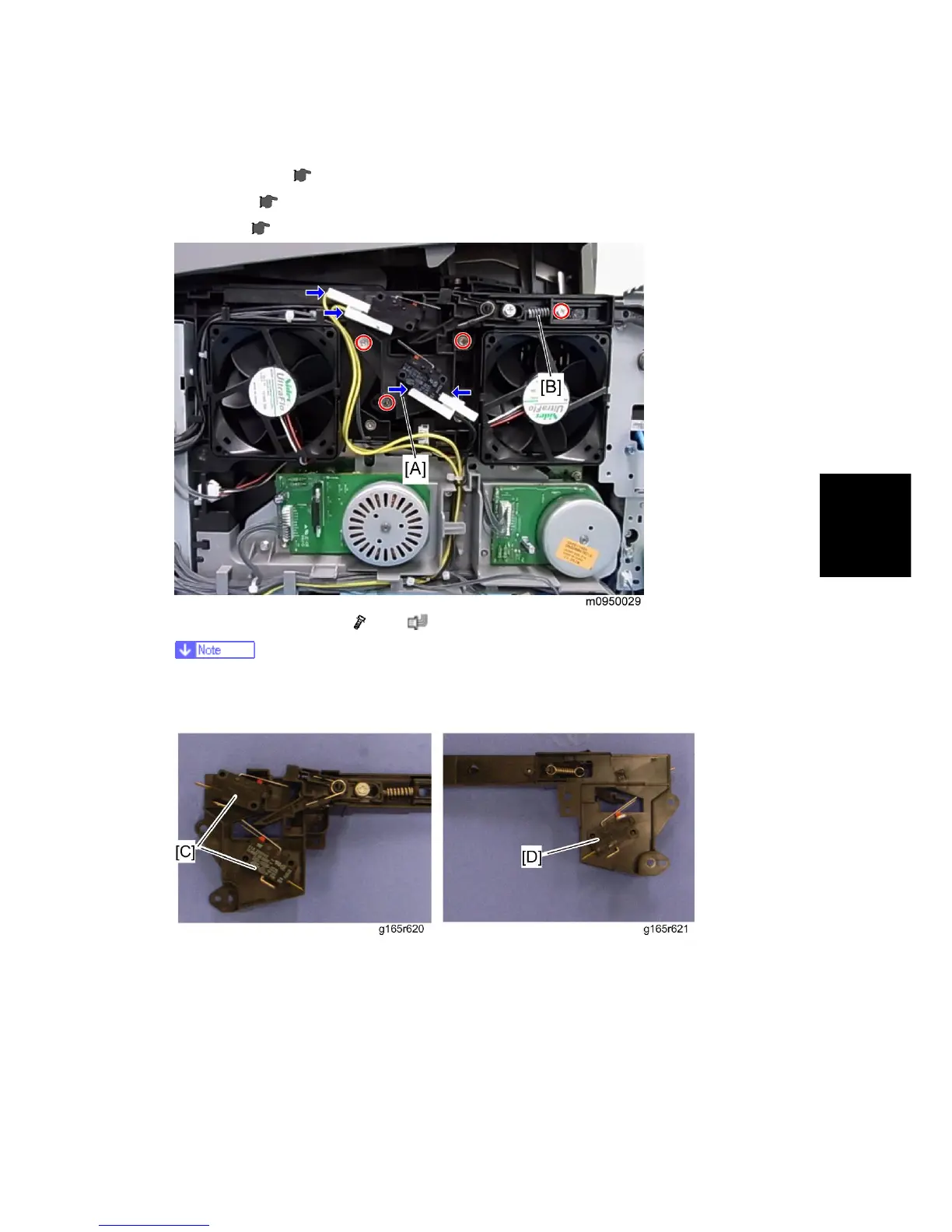
4.11.4 INTERLOCK SWITCHES
1. Operation panel ( p.4-6)
2. Rear cover (
p.4-5)
3. Left cover (
p.4-8)
4. Interlock switch base [A] (
x 4, x 4)
Removing the spring [B] first makes this procedure easier.
Remove all the connectors after the interlock switch base has been removed.
5. Two interlock switches [C] at the outside of the base and one interlock switch [D] at the
inside of the base (hooks x 2)