Electrical Components
SM 4-69 M095/M096/M099/M100
Replacement
and
Adjustment
4.11.9 ID CHIP BOARD
1. Operation panel ( p.4-6)
2. Rear cover (
p.4-5)
3. Left cover (
p.4-8)
4. Controller box cover (printer model:
p.4-54) or FCU and Speaker bracket (MF model:
p.4-54)
5. Disconnect the connector (CN305) on the EGB.
6. Interlock switch base (
p.4-63)
7. Fusing fan base (
p.4-64)
8. Drive unit (
p.4-19)
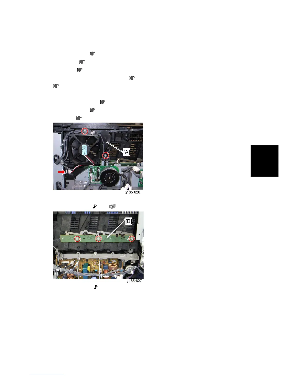
9. Take the harnesses aside around the LSU fan base [A].
10. LSU fan base [A] (
x 2, x 1)
11. ID Chip Board [B] (
x 3)
 Loading...