Guide to the Equipment
9
1
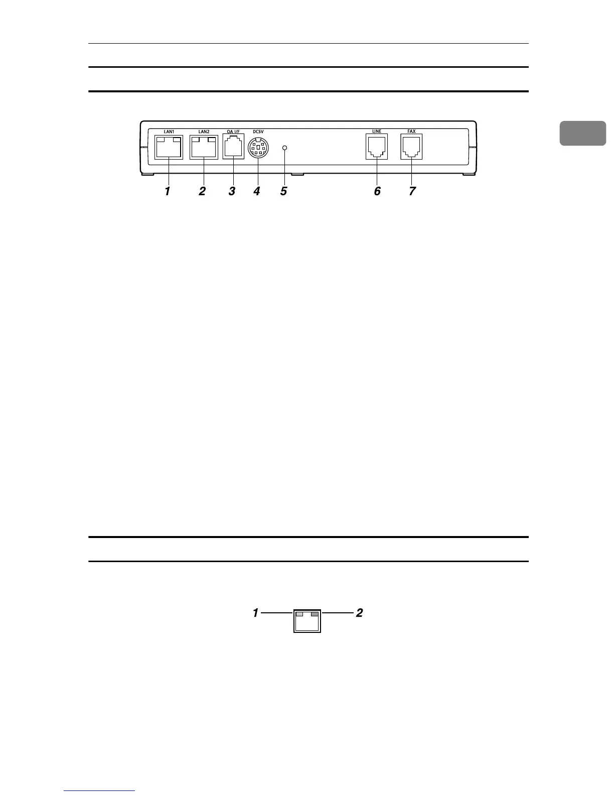
Remote Communication Gate Type BM1
1. LAN1 Port
The network (Ethernet) interface port for
maintenance. The IP address of the port
is set at 192.168.10.1 as the factory de-
fault, but you can change the address to
192.168.1.1 or 192.168.250.1. This is used
by the service engineer for the mainte-
nance of this equipment, and also used
for the first LAN2 port IP address setting
by the administrator.
2. LAN2 Port
The network interface port to connect
this equipment to the network. The de-
fault IP address is 192.168.0.2, but it can
be changed.
3. OA I/F
This is an RS-485 interface port to be con-
nected to the image I/O devices to collect
information without connection setting
via Network. The modular cable (black)
is used for the connection. Contact your
service representative for the connection
service. The actual connection operation
is to be conducted by your service repre-
sentative.
4. Power Socket
Connect to the power cable.
5. Screw Hole
A hole for a screw to set the bracket.
6. LINE
Interface port to connect the telephone
line.
7. FAX
Interface port to connect the FAX line
when using the same line with your FAX.
LAN Port Indicator
You can check the connection condition of the LAN1 port and the LAN2 port.
1. Orange
This color lights on when connected to
the 100 Mbps network. Lights off when
connected to the 10Mbps network or is
not connected to the network.
2. Green
This color lights on while transmitting
data.
AAA015S
AAA017S