Chapter 2
TECHNICAL INFORMATIONS
- 8 -
English
C224153200.fmIDM
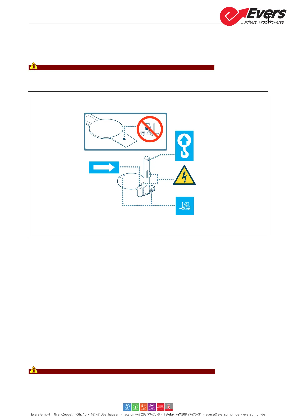
2.5. SIGNAL POSITION
The figure illustrates the position of the safety signals. Their meaning is explained in
"information and safety signals".
Check that the plates are clearly readable, and, if necessary, replace them with
new ones that shall be positioned in the same places as previously.
2.6. DESCRIPTION OF THE ELECTRICAL DEVICES
The figure shows the positioning of the devices on board of the machine.
A)Gear motor: activates table rotation.
B)Gear motor: activates movement of the spool carriage
C)Micro switch: detects the "high" spool carriage limit switch
D)Micro switch: detects the "low" spool carriage limit switch
E)Ph
otocell: detects the presence and the height of th
e load to be wrapped.
F) Mic
ro switch: starts phase stopping of the turntable
G)Sensor: detects the tension of the film during wrapping and enables the adjustment
of the speed of the pre-stretch rollers.
H)Electric motor: starts the pre-stretch rollers and is fitted with inverter (M), which
controls its speed. (Only for machines model "Ecoplat PPS - Ecoplat TP PPS")
L) Sensor: enables the in phase stop of the rotary table.
For further details consult the wiring diagram.
Evers GmbH Graf-Zeppelin-Str. 10 46149 Oberhausen Telefon +49 208 99475-0 Telefax +49 208 99475-31 evers@eversgmbh.de eversgmbh.de