146 Rockwell Automation Publication 1769-UM021I-EN-P - May 2018
Chapter 7 Use I/O Modules with CompactLogix 5370 L1 Controllers
• This section assumes that any DIN rail you use has been grounded
following Industrial Automation Wiring and Grounding Guidelines,
publication 1770-4.1
.
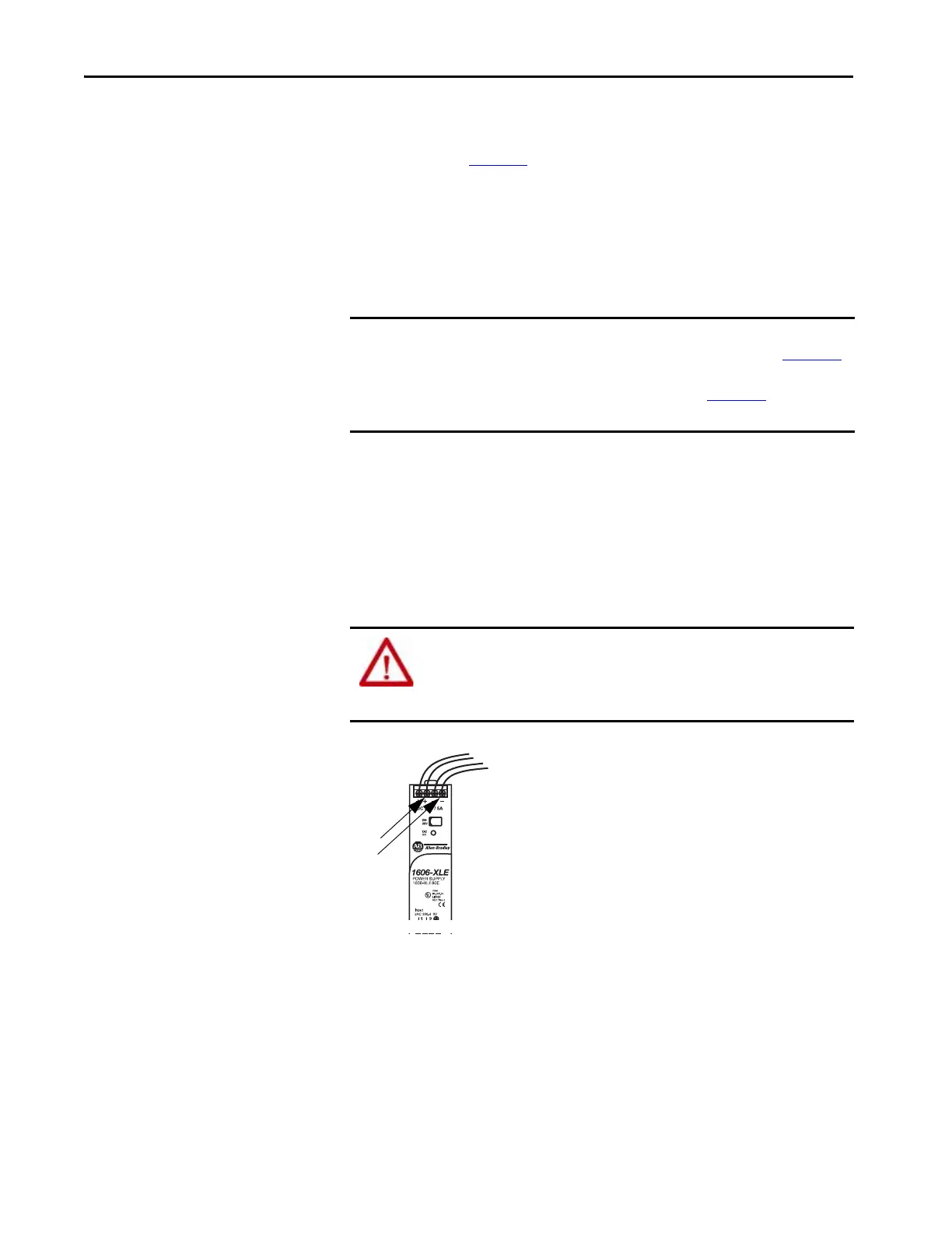
• For example purposes, this section describes how to use a
1606-XLE80E, Class 2 switched-mode power supply with the FP+ and
FP- terminals. The exact steps for other external power supplies can vary
from the steps that are described here.
Complete these steps to connect power to the CompactLogix 5370 series B
L16ER, L18ER, L18ERM, and series A L19 controllers.
1. Verify that the separate external 24V DC power source that powers the
CompactLogix 5370 L1 controller is not powered.
2. Connect wires to the + and - connections on the external 24V DC
power source.
IMPORTANT Do not use the following steps to connect power to the CompactLogix 5370
series A L16ER, L18ER, and L18 ERM controllers controller. See Appendix C
for steps to connect power to the CompactLogix 5370 series A L16ER, L18ER,
and L18 ERM controllers controller. The steps in Appendix C
provide an
optional way to connect power to a series B L1 controller.
WARNING: If you connect or disconnect wiring while the field-side power is
on, an electrical arc can occur. This could cause an explosion in hazardous
location installations. Be sure that power is removed or the area is
nonhazardous before proceeding.
 Loading...


