EasyManuals Logo

Rockwell Automation Allen-Bradley 1769-L24ER-QBFC1B User Manual

Rockwell Automation Allen-Bradley 1769-L24ER-QBFC1B
332 pages
To Next Page IconTo Next Page
To Previous Page IconTo Previous Page
Page #184 background imageLoading...
Page #184 background image
184 Rockwell Automation Publication 1769-UM021I-EN-P - May 2018
Chapter 8 Use I/O Modules with CompactLogix 5370 L2 Controllers
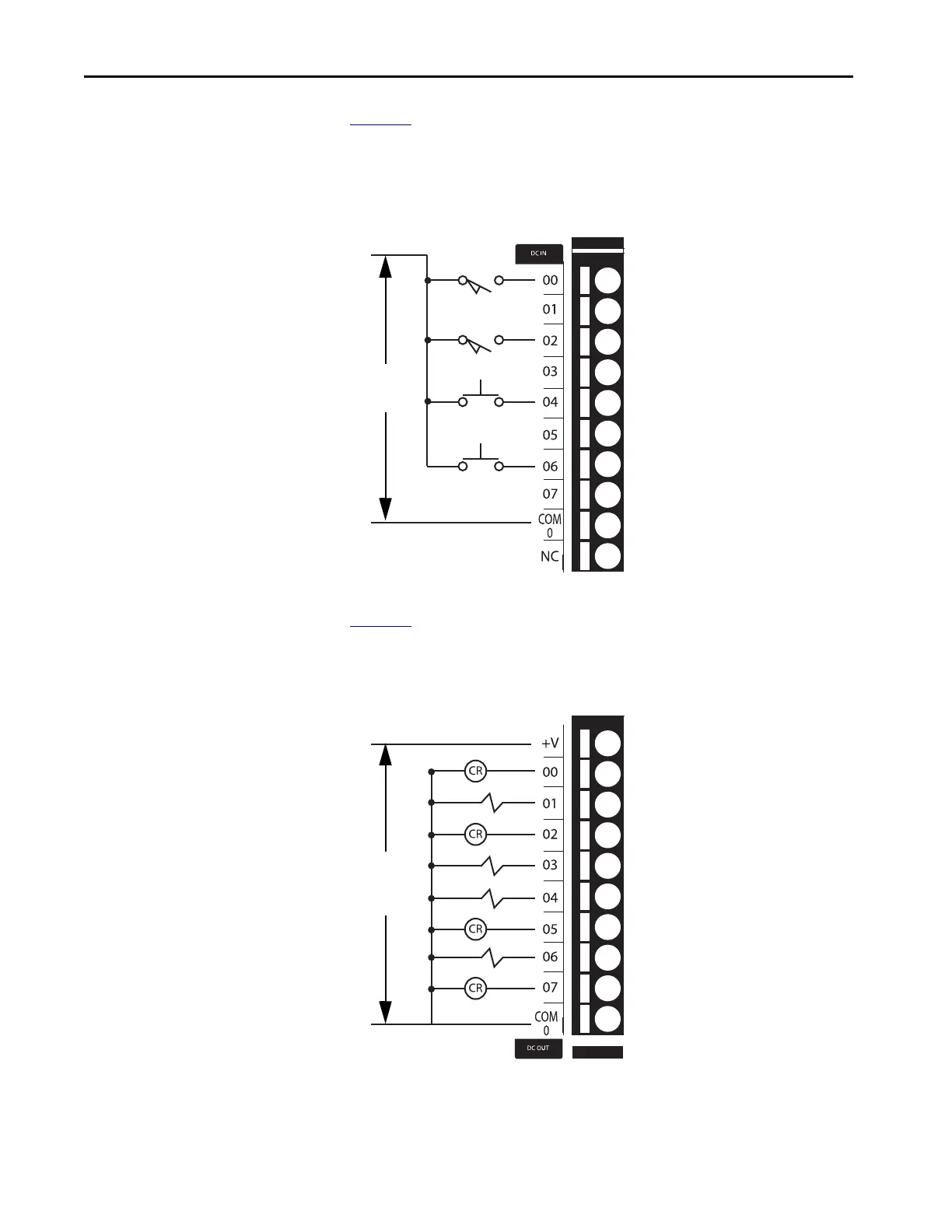
Figure 26 shows an example wiring diagram for the embedded digital input
points.
Figure 26 - CompactLogix 5370 L2 Controllers Embedded Digital Input Point Wiring Diagram
Figure 27 shows an example wiring diagram for the embedded digital output
points.
Figure 27 - CompactLogix 5370 L2 Controllers Embedded Digital Output Point Wiring Diagram
+ DC (Sinking)
- DC (Sourcing)
- DC (Sinking)
+ DC (Sourcing)
24V DC
+ DC
24V DC
- DC

Table of Contents

Questions and Answers:

Question and Answer IconNeed help?

Do you have a question about the Rockwell Automation Allen-Bradley 1769-L24ER-QBFC1B and is the answer not in the manual?

Rockwell Automation Allen-Bradley 1769-L24ER-QBFC1B Specifications

General IconGeneral
BrandRockwell Automation
ModelAllen-Bradley 1769-L24ER-QBFC1B
CategoryController
LanguageEnglish

Related product manuals