Rockwell Automation Publication 1769-UM021I-EN-P - May 2018 245
Use I/O Modules with CompactLogix 5370 L3 Controllers Chapter 9
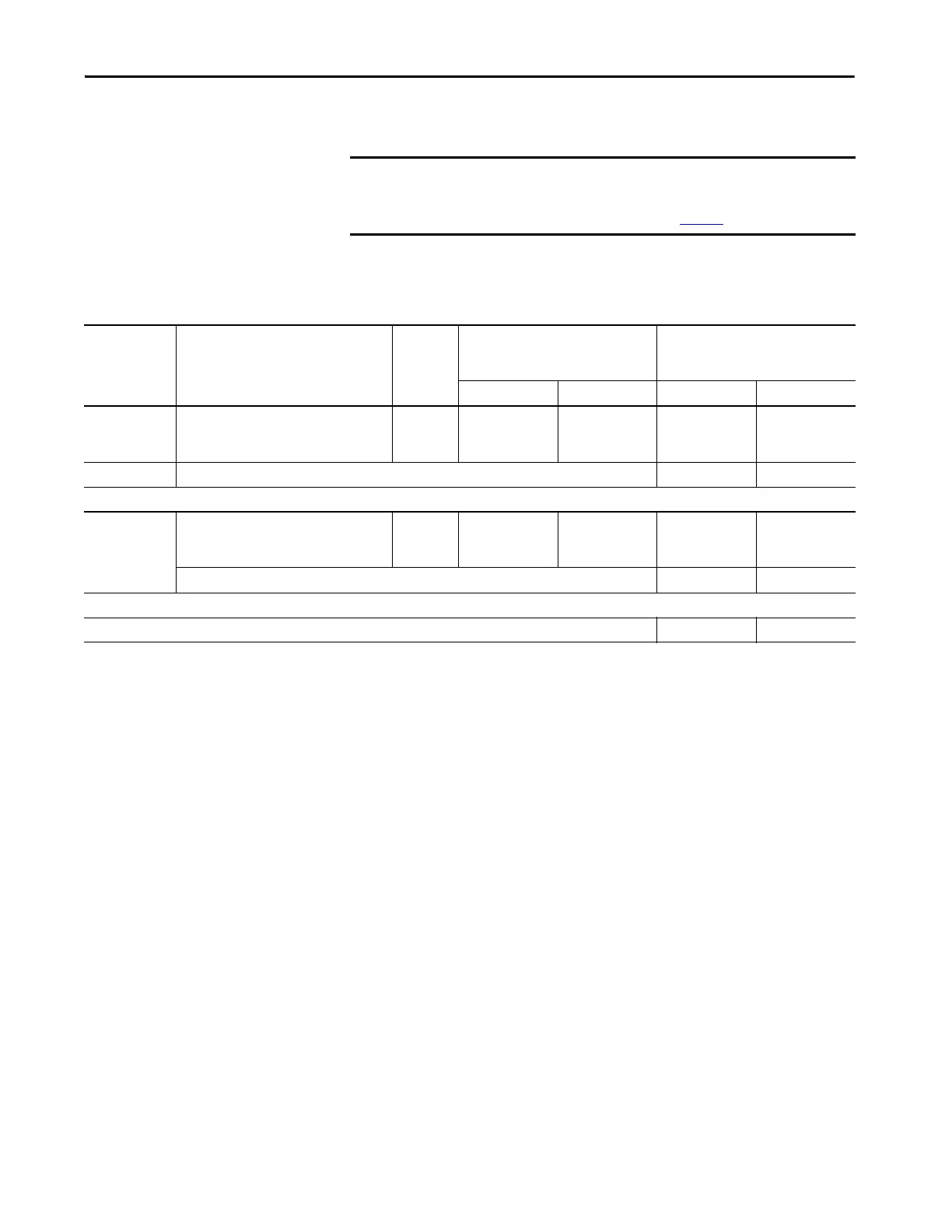
Calculate Power Consumption in an Additional Bank
Use this table to calculate power consumption in an extra bank.
IMPORTANT In extra banks, you can install I/O modules to the left side, right side, or both
sides of the power supply.
The system design determines how to use Table 31
.
Table 31 - Module Power Consumption Calculation for an Additional Bank
Side of Power
Supply
Device Cat. No. Number of
Modules
(3)
Module Current Requirements Calculated Current =
(Number of Modules) x (Module
Current Requirements)
at 5V DC (in mA) at 24V DC (in mA) at 5V DC (in mA) at 24V DC (in mA)
Left - Optional in
an extra bank
I/O Modules
IMPORTANT: Insert a separate row in this
calculation for each I/O module.
Up to 8 Module-specific Module-specific
Total Current Required
(2)
:
Right - Optional in
one bank
I/O Modules
IMPORTANT: Insert a separate row for each I/O
module.
Up to 8 Module-specific Module-specific
Total Current Required
(2)
:
Total Current Required for Bank if Modules Are Installed on Both Sides of the Power Supply
(1)
:
(1) This number must not exceed the power supply current capacity for the bank.
(2) This number must not exceed the power supply current capacity for this side of the bank.
(3) You can install up to eight modules in additional banks if the power supply distance ratings for the modules validate the system design.
 Loading...


