116 Rockwell Automation Publication 5069-UM003B-EN-P - January 2020
Appendix A Module Tags
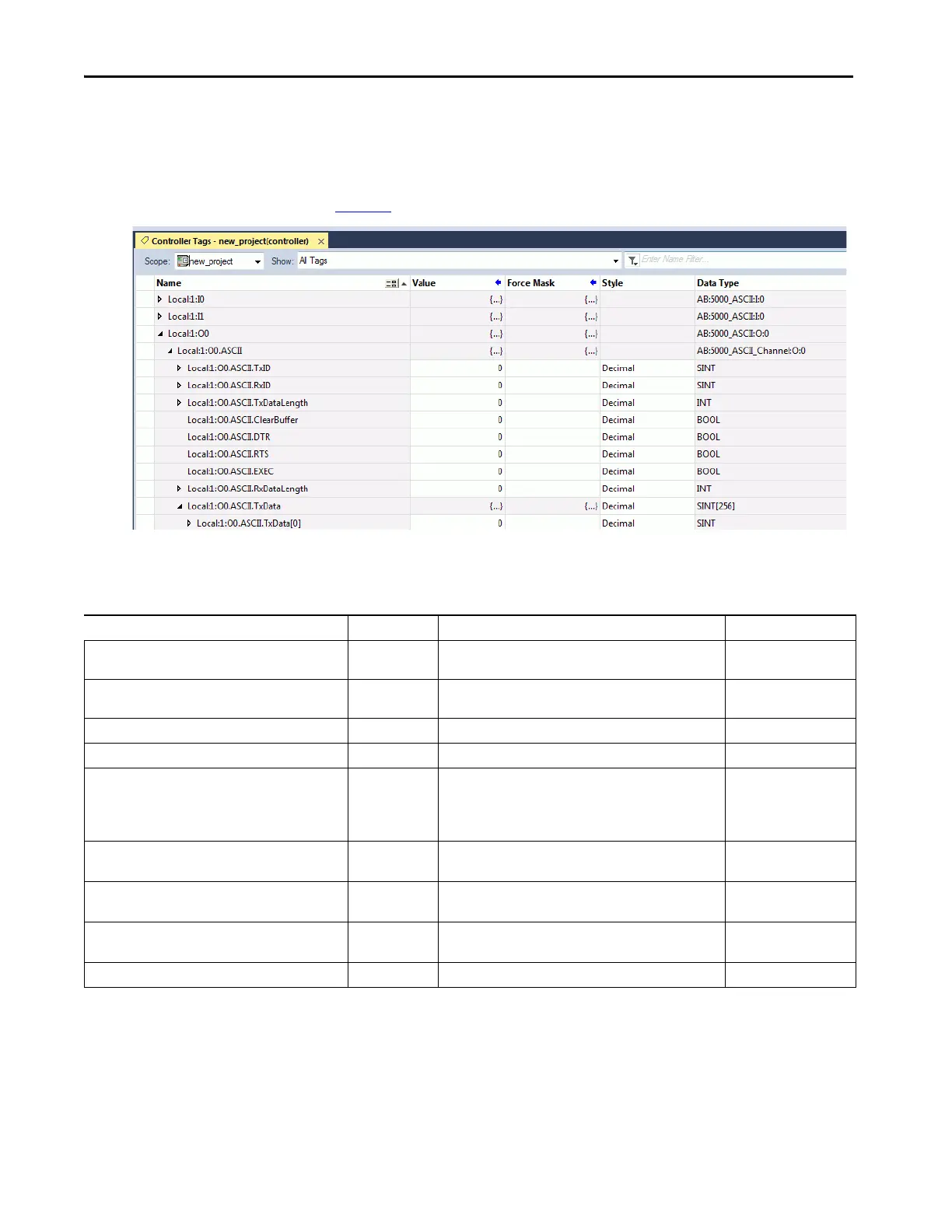
Output Tags
This screen capture shows the tags that are described in the following table.
Tab le 27
describes the output tags of channel 1 configured to the Generic ASCII
Table 27 - Generic ASCII Output Module Tags
Name Data Type Definition Valid Values
Ox.ASCII.TxID SINT This ID is incremented when you want to transmit data from the
serial port.
• -128…+127
(1)
Ox.ASCII.RxID SINT This ID is incremented when you receive data from the serial
port. It is only used in Master/Slave Handshake Mode.
• -128…+127
(1)
Ox.ASCII.TxDataLength INT Length of Transmitted Data of each channel. • 1…256
Ox.ASCII.RxDataLength INT Length of Received Data of each channel. • 1…256
Ox.ASCII.ClearBuffer BOOL If Clear Buffer the bit changes from 0 to 1, the Receive and
Transaction buffer is cleared.
In Half Duplex, the RTS signal level is cleared (set to Inactive)
When it is at 0: Clearbuffer is triggered.
•0 = No Change
• 1 = Buffer Cleared
Ox.ASCII.DTR BOOL Signal level of DTR line sent out when rising edge of EXEC bit is
detected.
•0 = Inactive
•1 = Active
Ox.ASCII.RTS BOOL Signal level of the RTS line sent out when rising edge of EXEC bit
is detected.
•0 = Inactive
•1 = Active
Ox.ASCII.EXEC BOOL If EXEC bit changes 0 to 1, FW will output a signal level that is set
in the DTR/RTS tag.
•0 = Inactive
•1 = Active
Ox.ASCII.TxData[x] SINT (256) Output data from module. • -128…+127
(1) The value of 0 must be skipped except during module power-up.

 Loading...


