Rockwell Automation Publication 5069-UM003B-EN-P - January 2020 117
Module Tags Appendix A
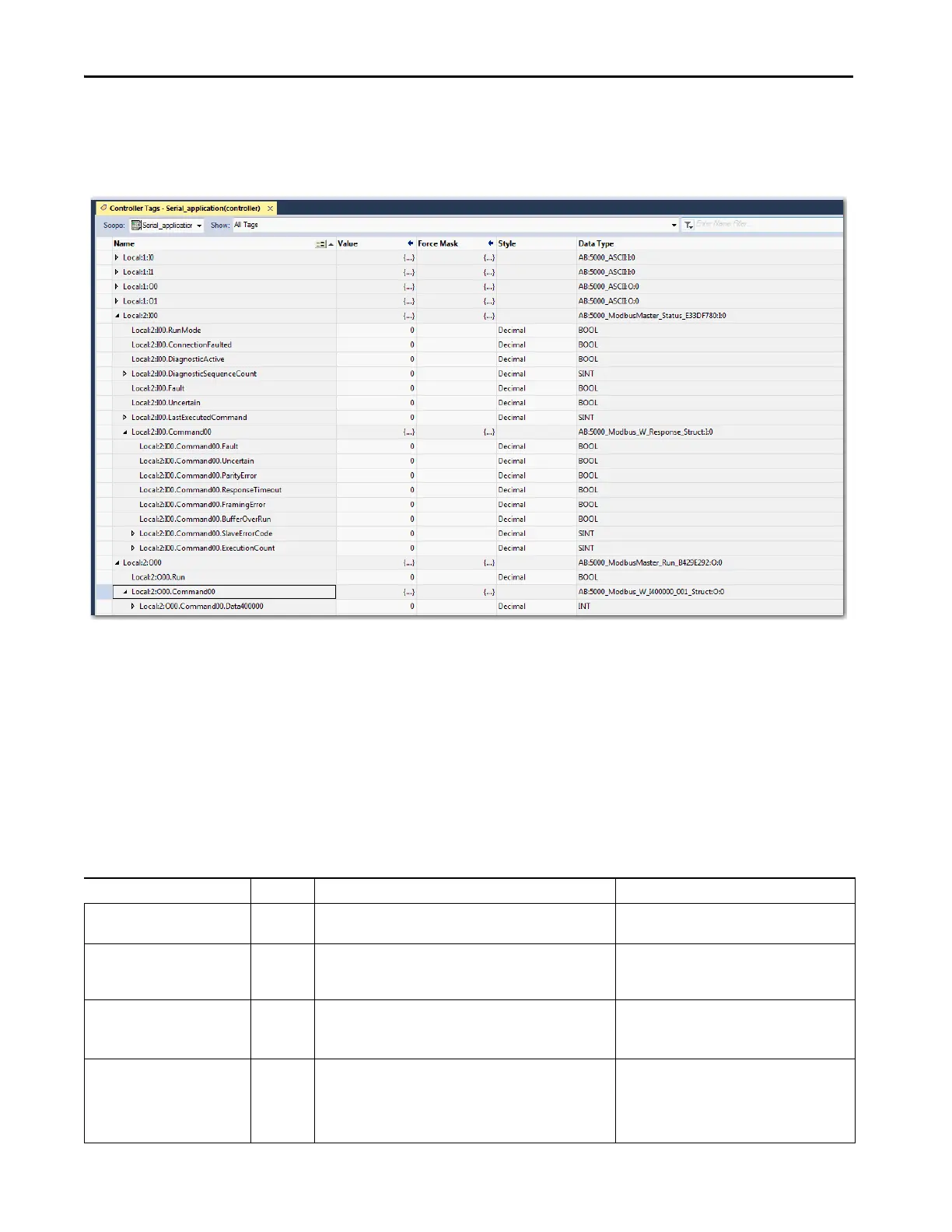
Channel Configured for
Modbus Master
This screen capture shows the tags that are described in the following tables.
Input Tags
In the following table, the xx in the tag names represents the channel number
because the module has two channels, and both channels support the use of
Modbus Master.
TIP The yy in the tag names represents the Modbus Master command number
and the zzzzzz represents the Modbus data address.
Table 28 - Modbus Master Input Tags
Name Data Type Definition Valid Values
Ixx.RunMode BOOL Channel’s operating state • 0 = Idle
•1 = Run
Ixx.ConnectionFaulted BOOL Indicates if a connection is running.
The module sets this tag to 0 when connected. If the module is not
connected, it changes the tag to 1.
•0 = Connection running
• 1 = Connection not running
Ixx.DiagnosticActive BOOL Indicates if any diagnostics are active or if the prognostics threshold
is reached.
• 0 = No diagnostics active
• 1 = One or more diagnostics are active or the
prognostics threshold is reached
Ixx.DiagnosticSequenceCount SINT Increments for each time a distinct diagnostic condition is detected,
and when a distinct diagnostic condition transitions from detected
to not detected.
Set to zero by product reset or power cycle. Wraps from 255 (-1) to 1
skipping zero.
-128…+127
The value of 0 is skipped except during module
power-up.

 Loading...


