122 Rockwell Automation Publication 5069-UM003B-EN-P - January 2020
Appendix A Module Tags
Output Tags
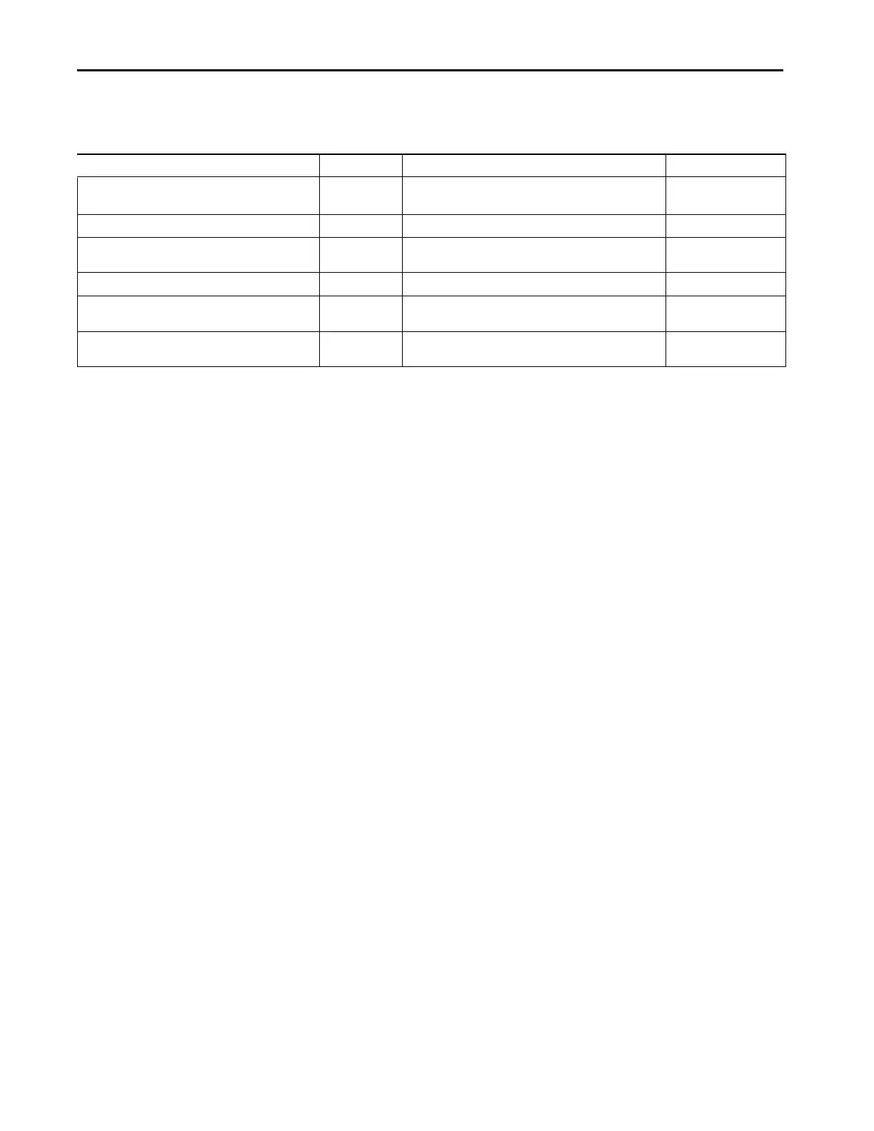
Table 31 - Modbus Slave Output Tags
Name Data Type Definition Valid Values
Ox.Slave.Run BOOL Channel’s operating state • 0 = Idle
•1 = Run
(5)
Ox.Slave.SequenceNumber INT Sequence number for updating slave data from controller • -32768…+32767
Ox.Slave.HoldingRegister[x]
(1)
INT Location of holding register values defined by user for the serial
module
• -32768…+32767
Ox.Slave.Coil[x]
(2)
SINT Location of slave coil values defined by user for the serial module • -128…+127
Ox.Slave.InputRegister[x]
(3)
INT Location of input register values defined by user for the serial
module
• -32768…+32767
Ox.Slave.DiscreteInput[x]
(4)
SINT Location of discrete input values defined by user for the serial
module
• -128…+127
(1) X represents any possible value 0…99
(2) X represents any possible value 0…15
(3) X represents any possible value 0…99
(4) X represents any possible value 0…15
(5) The Run bit is to start the update of the output (O) tags values into the Serial module. The serial module will always respond to the external Modbus master, but they will be using the old values if the
RUN bit is not enabled but new data is on the output O tag.

 Loading...


