Rockwell Automation Publication 1426-UM001J-EN-P - August 2019 11
PowerMonitor 5000 Unit Overview Chapter 1
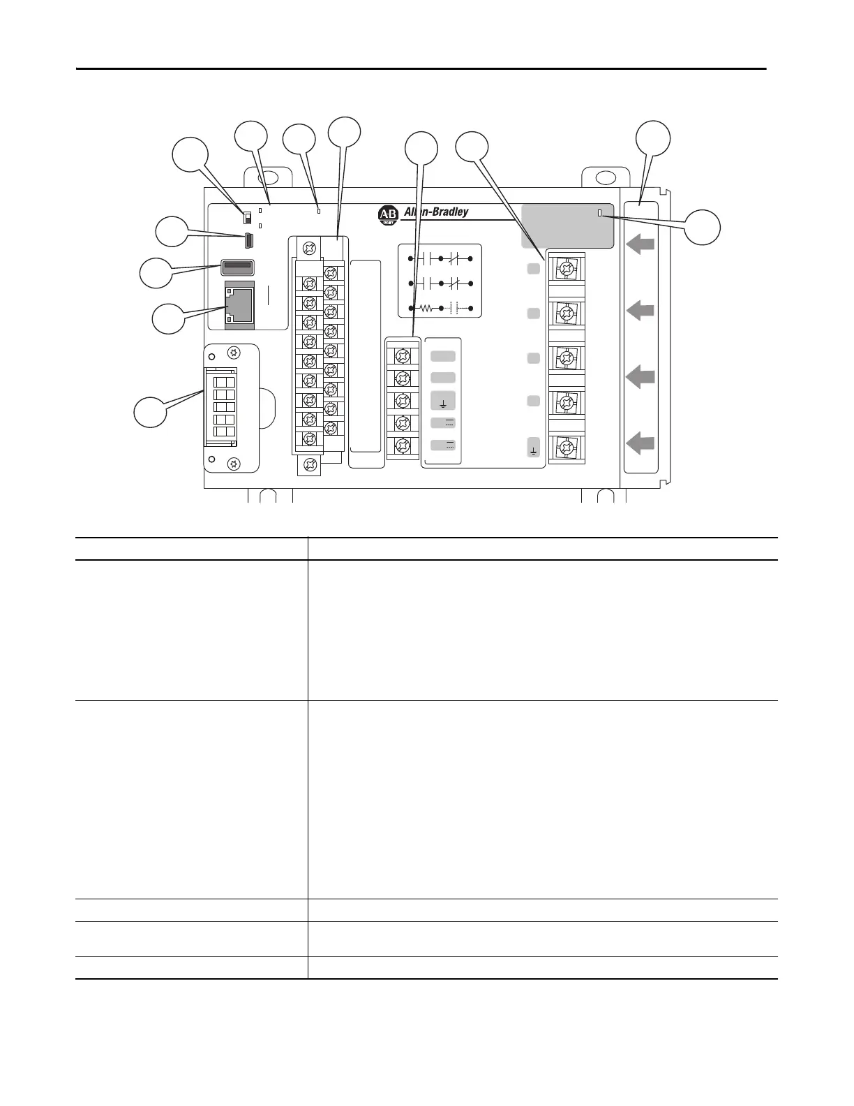
Figure 1 - Hardware Features
Virtual Wiring
Correction
---- S1
S2
---- S3
S4
---- S com
S com
---- K
Y
---- Z
R1 O
---- R1 com
R1 C
---- R2 O
R2 com
---- R2 C
R3 O
---- R3 com
R3 C
Module
status
Network
status
Cong Lock
EtherNet √IP
PowerMonitor 5000
Power
USB
Device
USB
Host
LNK
ACT
I 1
I 2
I 3
I 4
L1
L2
GND
24V
com
Scom
S n
Internal
24 VDC
K
Y
Z
Rx O
Rx com Rx C
Table 1 - Hardware Features
Feature Description
1. Ethernet port – standard RJ45 jack with status
indicators
Ethernet port hardware is included on all models. These protocols and functions are supported:
• EtherNet/IP™ network
• HTML web page for configuration and data access
Ethernet indicators
•LNK indicator
– Solid GREEN: IP link established
– Off: No link established
• ACT indicator
– Flashing YELLOW: Data present on Ethernet port
– Off: No data activity present
2. Optional communication port DeviceNet® and ControlNet® networks
•Module Status
– OFF: No control power
– Flashing GREEN/RED: Self-test
– Flashing GREEN: Power monitor has not been configured
– GREEN: Power monitor is running
– Flashing RED: Power monitor has detected a recoverable minor fault
– RED: Power monitor has detected a non-recoverable major fault
•Network Status
– OFF: No control power
– Flashing GREEN/RED: Self-test
– Flashing GREEN: No CIP™ connection
– Solid GREEN: CIP connection established
– Flashing RED: CIP connection timed out
– Solid RED: Duplicate address detected
3. USB host port USB standard A receptacle. Not used in this model.
4. USB device port The USB device port is a USB Mini-B receptacle that accepts standard USB Mini-B plugs, for connection to a host device,
such as a notebook computer.
5. Configuration Lock switch When enabled, this switch helps prevent changes in configuration that can affect revenue accuracy.

 Loading...

