18 Rockwell Automation Publication 1426-UM001J-EN-P - August 2019
Chapter 2 Install the PowerMonitor 5000 Unit
Wire the PowerMonitor
5000 Unit
The PowerMonitor 5000 unit is equipped with screw terminals with pressure
plates and finger protection for the control power, I/O wiring, and voltage
connections. The I/O wiring block is removable.
Current sensing conductors are routed through openings in the power monitor
housing.
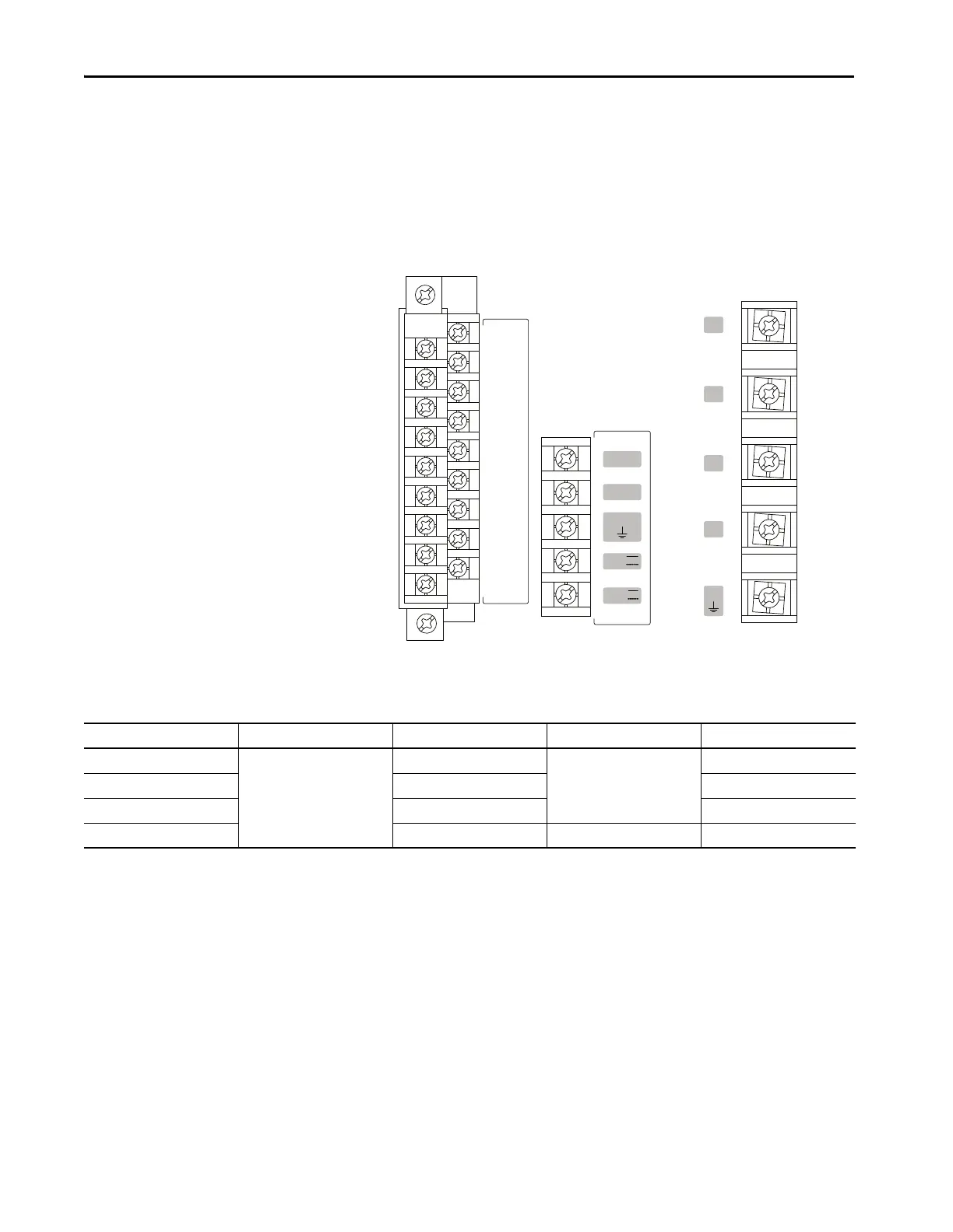
Figure 3 - Terminal Block Layout
Wire Requirements
Grounding
This product is intended to be mounted to a well-grounded mounting surface,
such as a metal panel. The upper mounting slots are equipped with protective
conductor terminals, which must make metal-to-metal contact with the
mounting panel. In solid-state systems, grounding helps limit the effects of noise
due to electromagnetic interference (EMI).
Connect a 2.5 mm
2
(14 AWG) wire from the GND terminal of the
PowerMonitor 5000 unit to the ground bus or other low-impedance earth
ground before you connect the control power or any other connections.
L1
L2
GND
24V
com
V1
V2
V3
VN
VG
---- S1
S2
---- S3
S4
---- S com
S com
---- K
Y
---- Z
R1 O
---- R1 com
R1 C
---- R2 O
R2 com
---- R2 C
R3 O
---- R3 com
R3 C
Wiring Category Wire Type Wire Size Range Wires Per Terminal Recommended Torque
Control Power Cu - 75 °C (167 °F) 0.25…2.5 mm
2
(22…14 AWG) 2 Max 1.27 N•m (11.24 lb•in)
Input/output (I/O) 0.5…0.8 mm
2
(20…18 AWG) 0.68 N•m (6 lb•in)
Voltage Sensing 0.75…2.5 mm
2
(18…14 AWG) 1.50 N•m (13.3 lb•in)
Current Sensing 4 mm
2
Max (12 AWG Max) 1 Max —

 Loading...

