242 Rockwell Automation Publication 1426-UM001J-EN-P - August 2019
Chapter 9 Communication
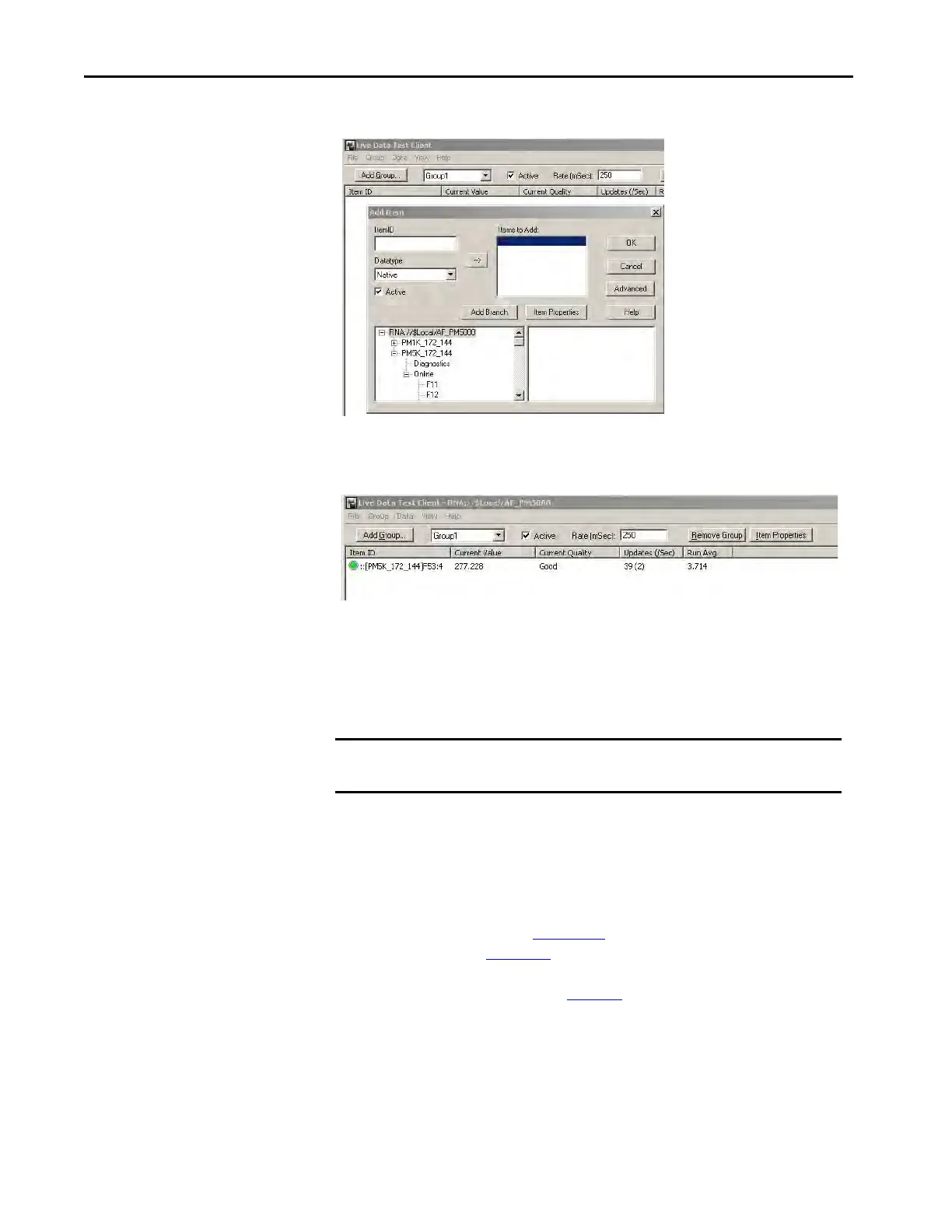
8. Find the address in the list, select it, and click OK.
The Test Client displays the data and other properties of the selected tag.
This example uses F53:4, V2_N_Volts.
Controller Applications:
Class 1 Connection
This section describes how to configure Class 1 connections with a Logix
controller and Studio 5000 Logix Designer® application and RSNetWorx
software.
Custom Add-on Profile Connection (Native EtherNet/IP units only)
The PowerMonitor 5000 unit can be configured with a Custom Add-on Profile
in Studio 5000 version 20 or later. The Custom Add-on Profile must be
downloaded and installed (see Appendix J
). For the setup and configuration of
the Add-on Profile, see Chapter 3
.
The summary of AOP data types in Tab le 3 3
provides an overview of the
module-defined Data Types that are created in the Logix project when a
PowerMonitor 5000 Add-on Profile is instantiated.
IMPORTANT Class 1 connections must be inhibited to update the power monitor
firmware.

 Loading...

