16 Rockwell Automation Publication 1426-UM001J-EN-P - August 2019
Chapter 2 Install the PowerMonitor 5000 Unit
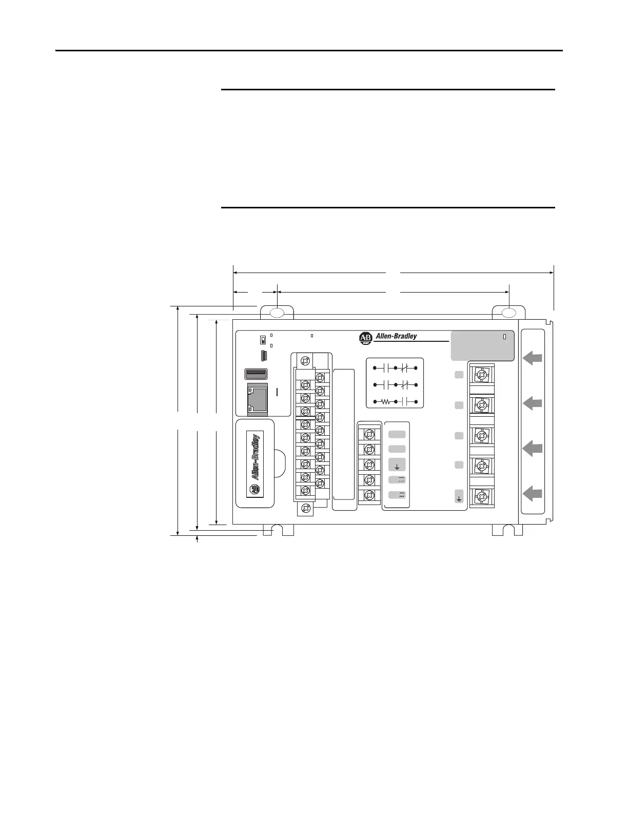
PowerMonitor 5000 Unit Dimensions
IMPORTANT Use caution not to block the ventilation slots of the power monitor. All
wiring, wireways, enclosure components, and other obstructions must be a
minimum of 50 mm (2.0 in.) from the top and bottom of the unit to provide
ventilation and electrical isolation. Units can be mounted side by side.
Access to the USB device port is required for initial configuration of the
power monitor and can be required for eventual administration and
maintenance. Consider safe and convenient access to the power monitor
front panel when planning the installation location.
Virtual Wiring
Correction
---- S1
S2
---- S3
S4
---- S com
S com
---- K
Y
---- Z
R1 O
---- R1 com
R1 C
---- R2 O
R2 com
---- R2 C
R3 O
---- R3 com
R3 C
Module
status
Network
status
Cong Lock
EtherNet/IP
Power
USB
Device
USB
Host
LNK
ACT
I 1
I 2
I 3
I 4
L1
L2
GND
24V
com
Scom
S n
Internal
24 VDC
K
Y
Z
Rx O
Rx com Rx C
V1
V2
V3
VN
VG
C O M M U N I C A T I O N P O R T
185
7.29
25
1.00
132
5.23
132
5.20
3.3
0.13
124
4.88
118
4.65
PowerMonitor 5000
Mounting Hole Tolerance:
±0.4 mm (0.016 in.)
Dimensions are in mm/in.
Depth: 178/7.0

 Loading...

