Rockwell Automation Publication 1426-UM001J-EN-P - August 2019 27
Install the PowerMonitor 5000 Unit Chapter 2
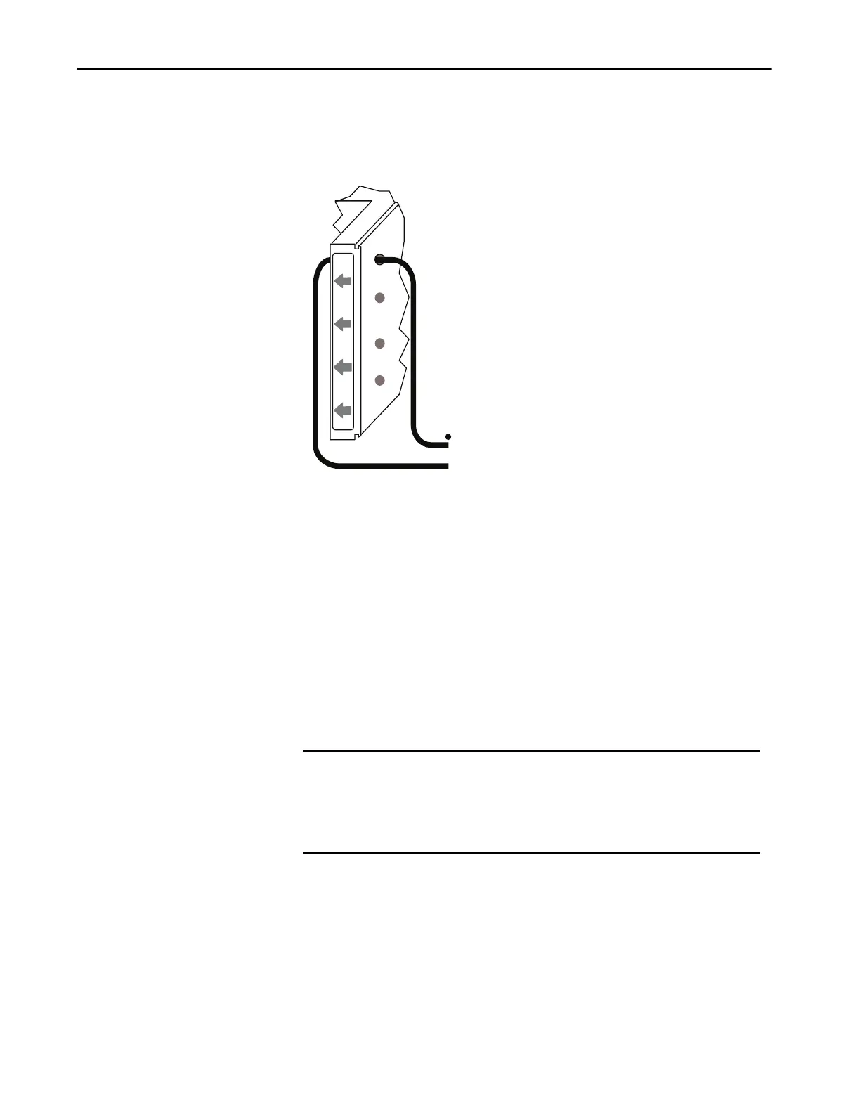
Current Sensing
Route the CT secondary wiring through the openings in the
PowerMonitor 5000 unit as shown.
Use a shorting terminal block (included in the 1400-PM-ACC accessory kit),
test block, or shorting switch (you provide) for CT wiring to permit safely
servicing connected equipment such as the PowerMonitor 5000 unit without de-
energizing the power system.
Use 2.5 mm
2
(14 AWG) or 3.3 mm
2
(12 AWG) (maximum) wiring between the
PowerMonitor 5000 unit and the shorting block. Use 2.5 mm
2
(14 AWG) or
larger wire between the shorting block and the CTs, depending on the length of
the circuit. Longer circuits require larger wire so that the wiring burden does not
exceed the CT burden rating and reduce system accuracy. The diameter of the
current sensing wiring openings is 7 mm (0.27 in.).
When wiring a PowerMonitor 5000 unit to existing CTs and metering devices,
wire the current sensing circuits of the PowerMonitor 5000 unit in series with the
CT secondary and current sensing circuits of the existing metering devices.
Do not install overcurrent protection or non-shorting disconnecting means in
CT secondary wiring. Connect the current sensing circuit to a low-impedance
earth ground at only one point.
IMPORTANT Ring lugs are recommended for making CT secondary connections. Standard
ring lugs do not pass through the current sensing openings of the
PowerMonitor 5000 unit. We recommend that the installer route the wire
from the shorting terminal block through the current sensing opening
before crimping on ring lugs.
To shorting terminal block
and current transformer (CT).
X1
X2
I1
I2
I3
I4

 Loading...

