The “raw“(unamplified) signals from the MCP contact and/or delay-line contacts are delivered to five LEMO 00 series type
connectors
*
.
Adjustable resistors (potis 0-200Ω) for “Holder” and “X” contact and for the MCP allow improving signal quality from an
MCP contact. The standard FT12TP decoupling plug has a switch for selecting the source of the MCP signal, i.e. optional pick-
up from MCP front contact or MCP back contact. The other side of the MCP is then connected to the terminating poti. An
in-line resistor can be adjusted from the side and changes the pulse height of the MCP signal but also alters the signal shape in
combination with the other potis. Fine-tuning these potis will result in a decent MCP signal shape adequate for further electronic
processing in follow-up timing electronics. Note that the signal outputs from MCP front and back can have different shapes
and require different fine-tuning. Any metal part (biased mesh, electrode) close to the MCP can affect the signal shape and it is
recommended to place a signal termination circuit on it, too. The “X”-line of the FT12TP poti.
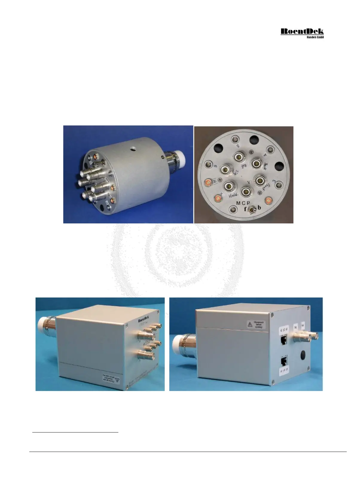
Figure 2.4: FT12TP Plug with switch for front (f) and back (b) MCP pickup.
The hole in the ring case allows access to the in-line poti.
The so-called FT12TPhex plug for the Hexanode is very similar to the FT12TP for DLD but has 6 lemo outputs for the delay-
line anode signals and two SHV bias inputs for U
ref
and U
sig
. It serves as connector/decoupling unit only for the Hexanode
while the bias and signal pickup to the remaining parts of the detector is routed via different feedthroughs and
decoupling/terminating circuits. The FT12TPhex circuit can also be supplied in a square-shaped case which contains more
flexible circuits, i.e. one can use an alternate biasing scheme for special detector setups and it allows a differential signal
transmission to special amplifiers via CAT7 cables, see Figure 2.5.
Figure 2.5: FT12TPhex plug with square case
When the FT12TP(hex) plug is connected to the delay-line it is possible verifying the absence of shorts between signal and
reference wires or some of the possible cabling errors on the vacuum side of the feedthrough: The resistance between U
ref
and
*
In case you have an older FT12TP plug for use with DLD with 6 lemo sockets (and 6 SHV connectors) please refer to the
manual that came with this delivery or ask
RoentDek for a manual of old-type FT12TP assemblies.
MCP Delay Line Detector Manual (11.0.1304.1) Page 27 of 83