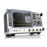
Instrument Tour
R&S
®
RTO
31Getting Started 1316.0833.02 ─ 10
Risk of electrical shock or fire
Voltages higher than 30 V RMS or 42 V peak or 60 V DC are regarded as hazardous
contact voltages. When working with hazardous contact voltages, use appropriate pro-
tective measures to preclude direct contact with the measurement setup:
●
Use only insulated voltage probes, test leads and adapters.
●
Do not touch voltages higher than 30 V RMS or 42 V peak or 60 V DC.
Risk of injury and instrument damage
The instrument is not rated for any measurement category.
Make sure that the input voltage on channel inputs does not exceed 200 V peak,
150 V RMS at 1 MΩ input impedance and 5 V RMS at 50 Ω input impedance.
Transient overvoltages must not exceed 200 V peak.
When performing measurements in circuits with transient overvoltages of category II,
III or IV circuits, make sure that no such overvoltages reach the R&S RTO input.
Therefore, use only probes that comply with DIN EN 61010-031. When performing
measurements in category II, III or IV circuits, it is mandatory to insert a probe that
appropriately reduces the voltage so that no transient overvoltages higher than
200 V peak are applied to the instrument. For detailed information, refer to the docu-
mentation and safety information of the probe manufacturer.
Explanation: According to section AA.2.4 of EN 61010-2-030, measuring circuits with-
out any measurement category are intended for measurements on circuits which are
not connected to the mains system.
3.1.10 Other Font Panel Connectors
Besides the input connectors, the instrument has USB connectors and probe compen-
sation connectors at the front panel.
USB
Two USB type A connectors that comply with standard USB 2.0. They are used to con-
nect devices like keyboard, mouse, printer and flash device to store and reload instru-
ment settings and measurement data. Also environment sensors can be connected to
measure and display temperature and other environment conditions.
Note: Electromagnetic interference (EMI) can affect the measurement results. To
avoid any impact, do not use USB connecting cables exceeding 1 m in length.
PROBE COMPENSATION
Probe compensation terminal to support adjustment of passive probes to the oscillo-
scope channel.
Protective earth conductor for grounding the instrument.
Front Panel

 Loading...


