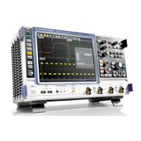
Instrument Tour
R&S
®
RTO
32Getting Started 1316.0833.02 ─ 10
Square wave signal for probe compensation with 1 kHz and 1 V
pp
.
Ground connector for probes.
AUX OUT
Output of the internal calibration signal, if the signal is configured to external destina-
tion.
3.2 Rear Panel
Figure 3-3 shows the rear panel of the R&S RTO with its connectors.
Fig. 3-3: Rear panel view of R&S
RTO
1 = AC power supply connector and main power switch
2 = LAN connector
3 = USB connectors
4 = DVI-D connector for external monitor
5 = External trigger input
6 = External trigger output
7a = Optional GPIB connector (option R&S RTO-B10, shown in figure)
7b = Optional connector for digital probe (Mixed Signal Option R&S RTO-B1, not shown in figure)
8 = Optional OCXO with input and output of the reference signal (option R&S RTOR&S RTO-B4)
9 = Optional exchangeable hard disk: solid state disk, option R&S RTO-B18 or standard hard disk drive,
option R&S RTO-B19
10 = Lugs to attach the accessory bag
11 = Kensington lock slot to secure the instrument against theft
Rear Panel
 Loading...


