Reference Manual
00809-0100-4360, Rev BA
August 2008
2-23
Rosemount 1151
Store the Information
5. Press both configuration buttons simultaneously for two seconds. The
meter displays “----” for approximately 7.5 seconds while the information
is being stored.
Set the Display Equivalent to a 4 mA Signal
6. Press the left button for two seconds.
7. To set the display numbers to a lower value, press the left configuration
button, and to set the display numbers to a higher value, press the right
configuration button. Set the numbers between –999 and 1000.
8. To store the information, press both configuration buttons simultaneously
for two seconds.
Set the Display Equivalent to a 20 mA Signal
9. Press the right button for two seconds.
10. To set the display numbers to a lower value, press the left configuration
button, and to set the display numbers to a higher value, press the right
configuration button. Set the numbers between –999 and 9999. The sum
of the 4 mA point and the span must not exceed 9999. The 20 mA value
must be greater than the 4 mA value.
11. To store the information, press both configuration buttons simultaneously
for two seconds. The LCD Display is now configured.
Replace the Cover
12. Make sure the rubber gasket is seated properly, replace the transparent
cover, and replace the retaining ring.
LCD Display Assembly
Figure 2-13 shows the mounting hardware required to properly install the LCD
Display on a transmitter or in the field signal indicator.
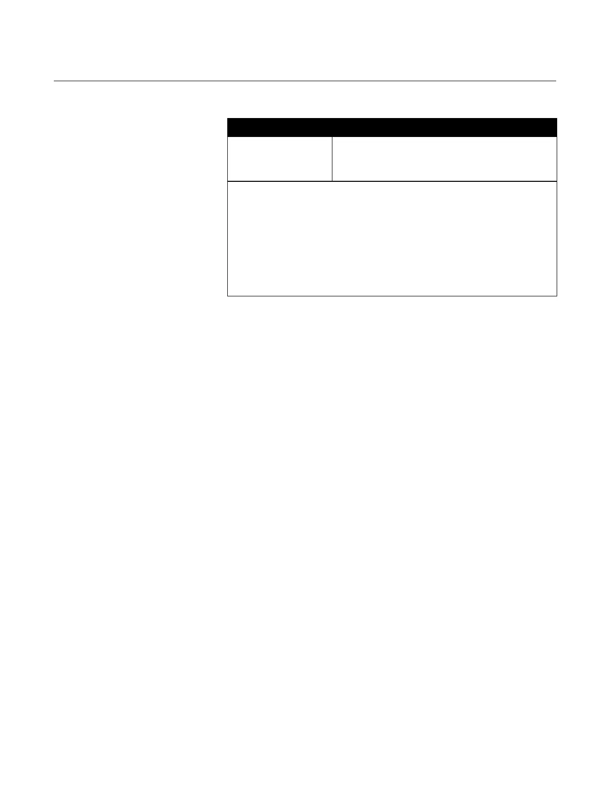
Table 2-3. LCD Display Modes.
Options Relationship between Input Signal and Digital Display
L in
L inF
Srt
SrtF
Linear
Linear with five-second filter
Square root
Square root with five-second filter
Square root function only relates to the digital display.
The bar graph output remains linear with the current signal.
Square root response
The digital display will be proportional to the square root of the input current where 4
mA=0 and 20 mA=1.0, scaled per the calibration procedure. The transition point from
linear to square root is at 25% of full scale flow.
Filter response operates upon “present input” and “input received in the previous five
second interval” in the following manner:
Display = (0.75 previous input) + (0.25 present input)
This relationship is maintained provided that the previous reading minus the present
reading is less than 25% of full scale.