29
Reference Manual
00809-0100-4809, Rev DA
Section 2: Installation
September 2015
Installation
Step 1: Determine the proper orientation
Refer to “Mounting” on page 8 for straight run requirements and orientation information.
Step 2: Drill a hole into the pipe
1. Determine the drill hole size based on the Sensor Size of Sensor Width.
2. Depressurize and drain the pipe.
3. From the previous steps, select the location to drill the hole.
4. Determine the diameter of the hole to be drilled according to the specifications in
Tabl e 2- 4 and drill the hole with a hole saw or a drill. Do not torch cut the hole.
5. If opposite-side support coupling is supplied, a second identically sized hole must be
drilled opposite the first hole so that the sensor can pass completely through the pipe.
To drill the second hole, follow these steps:
a. Measure the pipe circumference with a pipe tape, soft wire, or string (for the most
accurate measurement the pipe tape needs to be perpendicular to the axis of flow).
b. Divide the measured circumference by two to determine the location of the second
hole.
c. Re-wrap the pipe tape, soft wire, or string from the center of the first hole. Then,
using the number calculated in the preceding step, mark the center of what will
become the second hole.
d. Using the diameter determined from Tabl e 2- 4, drill the hole into the pipe with a
hole saw or drill. Do not torch cut the hole.
6. Deburr the drilled holes on the inside of the pipe.
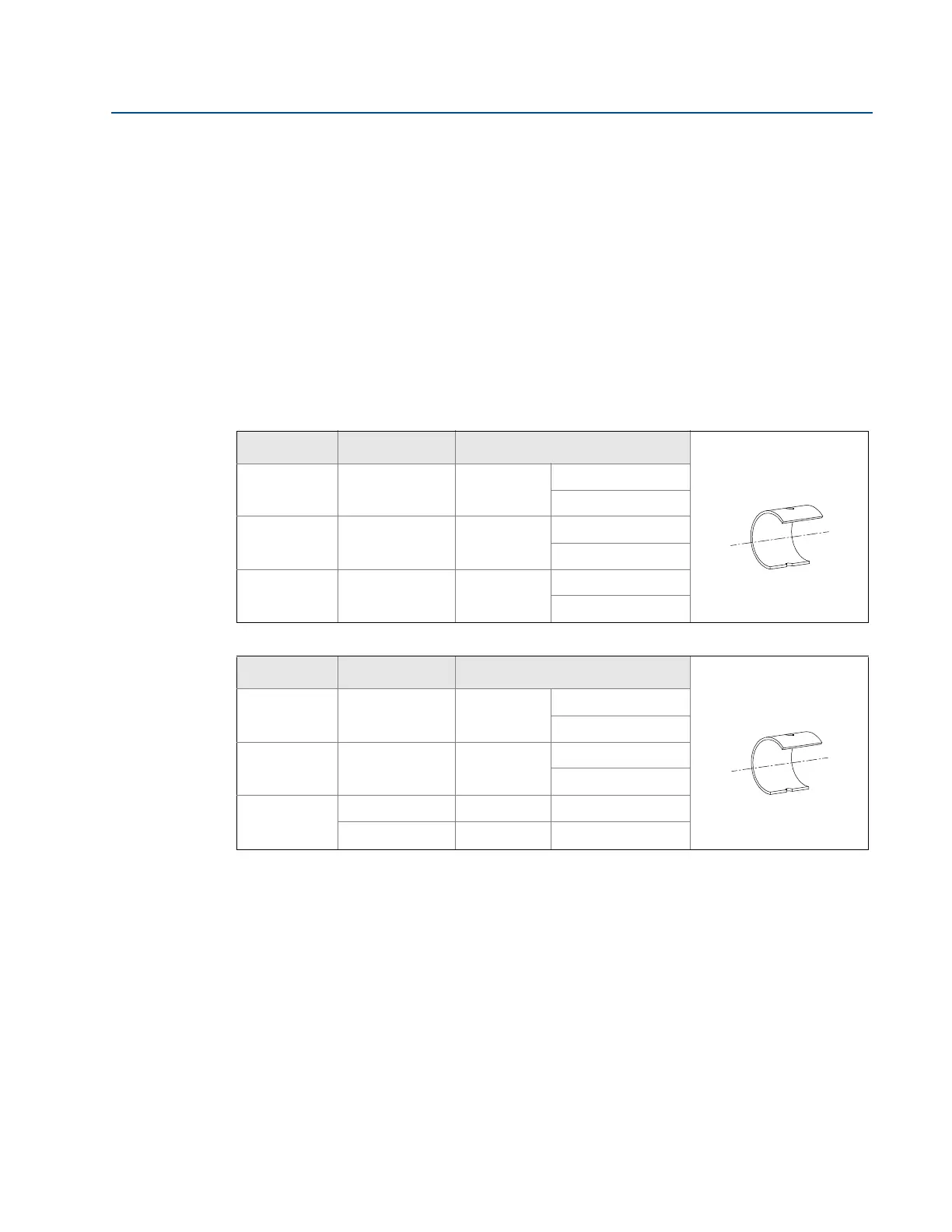
Table 2-4. 485 Sensor Size/Hole Diameter Chart
Sensor size Sensor width Hole diameter
1
0.590-in.
(14.99 mm)
3
/4-in.
(19 mm)
+
1
/32-in. (0.8 mm)
– 0.00
2
1.060-in.
(26.92 mm)
1
5
/16-in.
(34 mm)
+
1
/16-in. (1.6 mm)
– 0.00
3
1.935-in.
(49.15 mm)
2
1
/2-in.
(64 mm)
+
1
/16-in. (1.6 mm)
– 0.00
Table 2-5. 585 Sensor Size/Hole Diameter Chart
Sensor size Sensor width Hole diameter
11
0.80-in.
(20.32 mm)
7
/8-in.
(23 mm)
+
1
/32-in. (0,8 mm)
– 0.00
22
1.20-in.
(30.48 mm)
1
5
/16-in.
(34 mm)
+
1
/16-in. (1,6 mm)
– 0.00
44
2.30-in. 2
1
/2-in. +
1
/16-in. (1,6 mm)
(58.42 mm) (64 mm) – 0.00
Drill the appropriate diameter
hole through the pipe wall.
Note: Drill the hole 180° from
the first hole for opposite-
side support models.
Drill the appropriate diameter
hole through the pipe wall.
Note: Drill the hole 180° from
the first hole for opposite-
side support models.