30
Reference Manual
00809-0100-4809, Rev DA
Section 2: Installation
September 2015
Installation
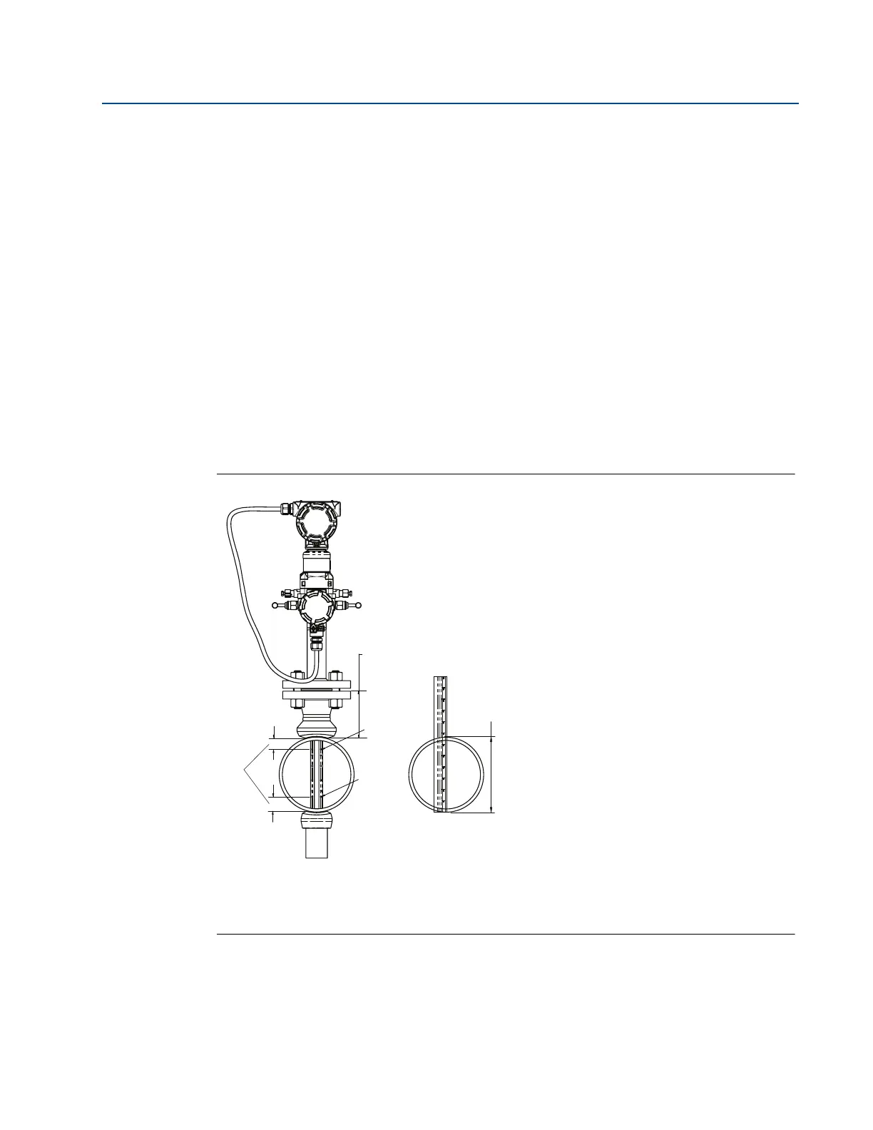
Step 3: Assemble and check fit-up
For accurate measurement, use the following steps to ensure that Ports A and B are equal
distances from the inside walls of the pipe.
1. Assemble the Annubar sensor to the mounting hardware with the gaskets and bolts.
2. Hand tighten the bolts just enough to hold the position of the sensor centered in the
mounting hardware.
3. Measure the distance from the high point of the weldolet to the first sensing hole, port
B, then subtract
1
/16-in. (1.6 mm).
4. Measure the distance from the end of the transferred length in Step 3 to the last sensing
hole, port A.
5. Compare the numbers obtained in Step 3 and 4.
Small discrepancies can be compensated for with the fit-up of the mounting hardware. Large
discrepancies may cause installation problems or error.
Figure 2-20. Fit-Up Check for Annubar Sensor with Opposite Side Support
A. The same within
1
/8-in. (3 mm)
B. ODF
C. Port B
D. Port A
E. Pipe outside diameter
A
B
C
D
E
 Loading...


