63
Reference Manual
00809-0100-4809, Rev DA
Section 3: Commissioning
September 2015
Commissioning
Periodic “zero” calibration and/or commissioning is recommended to maintain the accuracy of
Annubar sensor. The frequency of this type of maintenance should be established for each
individual application.
Liquid service 3-valve manifold
The following procedures assume the process pipe is pressurized to normal operating pressure
and should be followed to obtain a true zero at static or “pipe” pressure.
1. Open the high and low manifold valves MH and ML. Refer to Figure 3-1 for valve
designations.
2. Open the Equalizer valve ME.
3. Open the drain/vent valves on the transmitter DVH and DVL; bleed until no air is
apparent in the liquid.
4. Close both drain/vent valve DVH and DVL.
5. Close the low side manifold valve ML.
6. Check the transmitter zero by noting the output. If the signal reads outside of the range
3.98 mA to 4.02 mA then perform a zero trim procedure as described in the transmitter
manual.
7. After the zero trim, if the signal reads outside of the range 3.98 mA to 4.02 mA, repeat
Steps 1 - 6.
8. Close the Equalizer valve ME.
9. Open the low side valve ML and ensure that the high side valve MH is open.
10. The system is now operational.
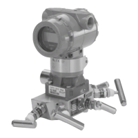
Figure 3-1. Valve Identification for Direct Mounted Annubar Sensor Models with 3-Valve
Manifold
 Loading...


