Reference Manual
00809-0100-4664, Rev BA
January 2010
6-5
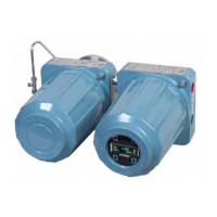
Rosemount 8712
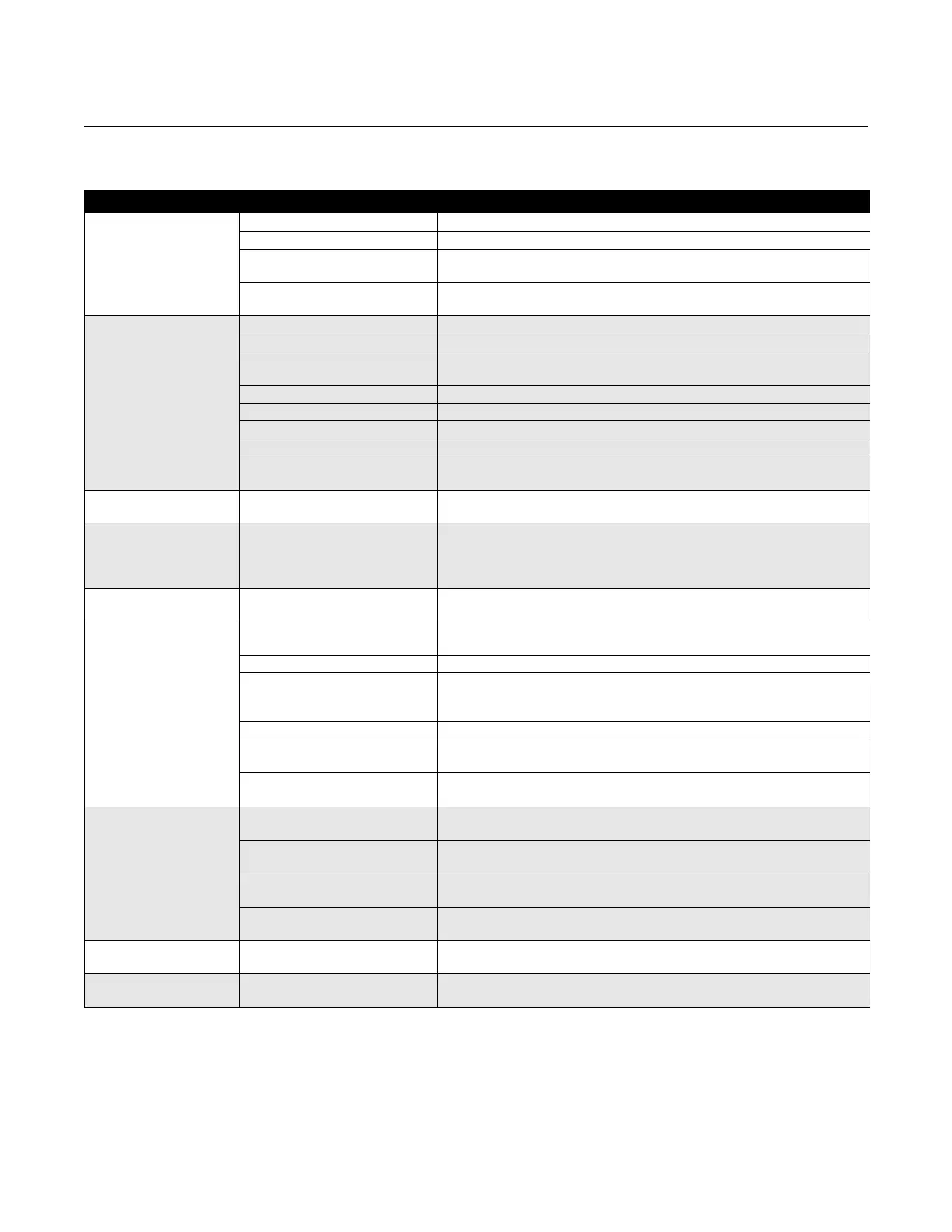
Table 6-4. Basic Troubleshooting–Rosemount 8712
Symptom Potential Cause Corrective Action
Output at 0 mA No power to transmitter Check power source and connections to the transmitter
Blown fuse Check the fuse and replace with an appropriately rated fuse, if necessary
Electronics failure Verify transmitter operation with an 8714 Calibration Standard or replace the
electronic board
Analog output improperly
configured
Check the analog power switch position
Output at 4 mA Open coil drive circuit Check coil drive circuit connections at the sensor and at the transmitter
Transmitter in multidrop mode Configure Poll Address to 0 to take transmitter out of multidrop mode
Low Flow Cutoff set too high Configure Low Flow Cutoff to a lower setting or increase flow to a value
above the low flow cutoff
PZR Activated Open PZR switch at terminals 5 and 6 to deactivate the PZR
Flow is in reverse direction Enable Reverse Flow function
Shorted coil Coil check – perform sensor test
Empty pipe Fill pipe
Electronics failure Verify transmitter operation with an 8714 Calibration Standard or replace the
electronic board
Output will not reach
20 mA
Loop resistance is greater than
600 ohms
Reduce loop resistance to less than 600 ohms
Perform analog loop test
Output at 20.8 mA Transmitter not ranged properly Reset the transmitter range values –
see “PV URV (Upper Range Value)” on page 3-11;
Check tube size setting in transmitter and make sure it matches your actual
tube size – see “Line Size” on page 3-10
Output at alarm level Electronics failure Cycle power. If alarm is still present, verify transmitter operation with an 8714
Calibration Standard or replace the electronic board
Pulse output at zero,
regardless of flow
Wiring error Check pulse output wiring at terminals 3 and 4. Refer to wiring diagram for
your sensor and pulse output
PZR activated Remove signal at terminals 5 and 6 to deactivate the PZR.
No power to transmitter Check pulse output wiring at terminals 3 and 4. Refer to wiring diagram for
your sensor and pulse output
Power the transmitter
Reverse flow Enable Reverse Flow function
Electronics failure Verify transmitter operation with an 8714 Calibration Standard or replace the
electronic board
Pulse output incorrectly
configured
Review configuration and correct as necessary
Communication problems
with the Handheld
Communicator
4–20 mA output configuration Check analog power switch (internal/external). The Handheld Communicator
requires a 4–20 mA output to function
Communication interface wiring
problems
Incorrect load resistance (250 minimum, 600 ohm maximum);
Check appropriate wiring diagram
Low batteries in the Handheld
Communicator
Replace the batteries in the Handheld Communicator – see the
communicator manual for instructions
Old revision of software in the
Handheld Communicator
Consult your local sales office about updating to the latest revision
of software
Error Messages on LOI or
Handheld Communicator
Many possible causes depending
upon the message
See the Figure 3-1 on page 3-3 for the LOI or Handheld Communicator
messages.
Digital input does not
register
Input signal does not provide
enough counts
Verify that the digital input provided meets the requirements of Figure 2-13
on page 2-15