Reference Manual
00809-0100-4664, Rev BA
January 2010
4-39
Rosemount 8712
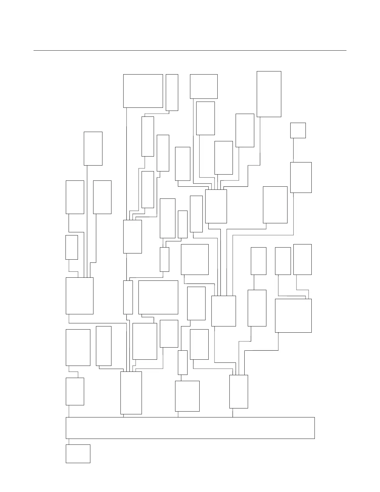
Figure 4-2. Field Communicator Menu Tree for the Rosemount 8712
1. Device
Setup
2. PV
3. PV Loop
Current
4. PV LRV
5. PV URV
1. PV
2. PV % Range
3. PV Loop Current
4. Totalizer Setup
5. Pulse Output
1. Totalizer Units
2. Gross Total
3. Net Total
4. Reverse Total
5. Start Totalizer
6. Stop Totalizer
7. Reset Totalize
1. Diagnostic Controls
2. Basic Diagnostics
3. Advanced Diagnostics
4. Diagnostic Variables
5. Trims
6. View Status
1. Process
Variables
2. Diagnostics
3. Basic
Setup
4. Detailed
Setup
5. Review
1. Self Test
2. AO Loop Test
3. Pulse Output Loop Test
4. Tune Empty Pipe
5. Electronics Temp
6. Flow Limit 1
7. Flow Limit 2
8. Total Limi
1. EP Value
2. Electronics Temp
3. Line Noise
4. 5 Hz SNR
5. 37 Hz SNR
6. Signal Power
7. 8714i Results
1. PV Units
2. Special Units
1. Volume Unit
2. Base Volume Unit
3. Conversion Number
4. Base Time Unit
5. Flow Rate Unit
1. Analog Output
2. Pulse Output
3. Digital I/O
4. Reverse Flow
5. Totalizer Setup
6. Alarm Levels
7. HART Out
1. PV URV
2. PV LRV
3. PV Loop Current
4. PV Alarm Type
5. AO Loop Test
6. D/A Trim
7. Scaled D/A Trim
8. Alarm Level
1. Pulse Scaling
2. Pulse Width
3. Pulse Output Loop Test
1. Totalizer Units
2. Gross Total
3. Net Total
4. Reverse Total
5. Start Totalizer
6. Stop Totalizer
7. Reset Totalize
1. Variable Mapping
2. Poll Address
3. # of Req Preams
4. # of Resp Preams
5. Burst Mode
6. Burst Option
1. Operating Mode
2. Man Config DSP
3. Coil Drive Freq
4. Low Flow Cutoff
5. PV Damping
1. Coil Drive Freq
2. Density Value
3. PV USL
4. PV LSL
5. PV Min S
an
1. Additional Params
2. Configure Output
3. Signal Processing
4. Universal Trim
5. Device Info
1. DI/DO 1
2. DO 2
3. Flow Limit 1
4. Flow Limit 2
5. Total Limit
6. Diagnostic Status Aler
1. Tag
2. Flow Units
3. Line Size
4. PV URV
5. PV LRV
6. Calibration Number
7. PV Dam
1. Flange Type
2. Flange Material
3. Electrode Type
4. Electrode Material
5. Liner Material
1. Manufacturer
2. Tag
3. Descriptor
4. Message
5. Date
6. Device ID
7. PV Sensor S/N
8. Flowtube Tag
9. Write Protect
- Revision No.
- Construction Materials
1. Universal Rev
2. Transmitter Rev
3. Software Rev
4. Final Assembly #
1. Status
2. Samples
3. % Limit
4. Time Limit
1. D/A Trim
2. Scaled D/A Trim
3. Digital Trim
4. Auto Zero
5. Universal Trim
1. 8714i Cal Verification
2. Licensing
1. Run 8714i Verification
2. 8714i Results
3. Flowtube Signature
4. Set Pass/Fail Criteria
5. Measurements
1. Signature Values
2. Re-Signature Meter
3. Recall Last Saved Values
1. License Status
2. License Key
1. Device ID
2. License Key
1. PV is
2. SV is
3. TV is
4. QV is
1. Coil Resistance
2. Coil Signature
3. Electrode Resistance
1. No Flow Limit
2. Flowing, Limit
3. Empty Pipe Limit
1. Test Condition
2. Test Criteria
3. 8714i Test Result
4. Simulated Velocity
5. Actual Velocity
6. Velocity Deviation
7. Xmtr Cal Test Result
8. Tube Cal Deviation
9. Tube Cal Test Result
- Coil Circuit Test Result
- Electrode Circuit Test
Resul
1. Test Condition
2. Test Criteria
3. 8714i Test Result
4. Simulated Velocity
5. Actual Velocity
6. Velocity Deviation
7. Xmtr Cal Test Result
8. Tube Cal Deviation
9. Tube Cal Test Result
- Coil Circuit Test Result
- Electrode Circuit Test
Resul
1. Total Control
2. Total Mode
3. Total High Limit
4. Total Low Limit
5. Total Limit Hysteresis
1. Control 2
2. Mode 2
3. High Limit 2
4. Low Limit 2
5. Flow Limit Hysteresis
1. Control 1
2. Mode 1
3. High Limit 1
4. Low Limit 1
5. Flow Limit Hysteresis
1. Configure I/O 1
2. DIO 1 Control
3. Digital Input 1
4. Digital Output 1
1. Coil Resistance
2. Coil Signature
3. Electrode Resistance
1. Total Control
2. Total Mode
3. Total High Limit
4. Total Low Limit
5. Total Limit Hysteresis
1. Control 2
2. Mode 2
3. High Limit 2
4. Low Limit 2
5. Flow Limit Hysteresis
1. Control 1
2. Mode 1
3. High Limit 1
4. Low Limit 1
5. Flow Limit Hysteresis
Empty Pipe On/Off
Process Noise On//Off
Grounding/Wiring On/Off
Electronics Temp On/Off
Process Noise Detect On/Off
Line Noise Detection On//Off
Digital I/O On/Off
8714i On/Off
Reverse Flow
Zero Flow
Transmitter Fault
Empty Pipe
Flow Limit 1
Flow Limit 2
Diag Status Alert
Totalizer Limi
Electronics Failure On/Off
Coil Open Circuit On/Off
Empty Pipe On/Off
Reverse Flow On/Off
Ground/Wiring Fault On/Off
High Process Noise On/Off
Elect Tem
Out of Ra .. On/Off
1. EP Value
2. EP Trig. Level
3. EP Counts