D-3
Appendix D
Although stray noise may be picked up with induced flow voltage at the
electrodes, it is easily separated by the following procedure:
1. Measure voltage with the magnetic field high and
note the amount.
2. Measure voltage with magnetic field low and note the amount.
3. Subtract the measured voltage in step 2 from that in step 1.
This difference is the actual flow voltage.
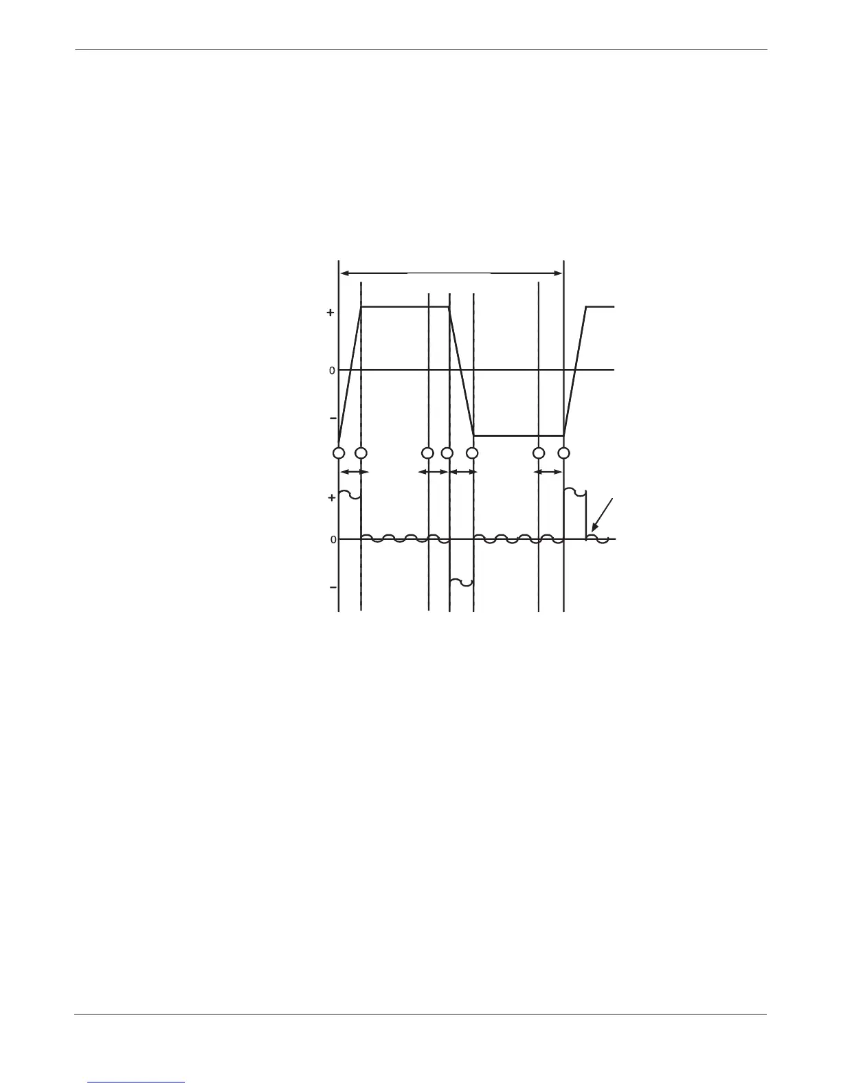
FIGURE D-2.
Pulsed dc Operation Sequence.
Figure D-2 illustrates events associated with the pulse event sequence.
In this sequence, the circuitry samples and corrects for noise-induced
flowtube voltage several times a second. The flow signal to the
transmitter is also safe from stray 50 or 60 Hz noise in the environment
because the sample period is equal in length to one power line cycle
(60 Hz). This allows the coil drive and signal wires to share the same
conduit using standard cables. The issues of reference voltage,
quadrature voltage, phase detection, and zero controls are not
applicable to pulsed dc systems.
EVENT SEQUENCE
➀ Magnetic Field Transition Begins.
➀–➁ Transients Present Due to Transition of Magnetic Field.
➁–➂ Magnetic Field and Flow Signal Stabilize.
➂–➃ Flow Signal Sampled.
➃ Magnetic Field Transition Begins.
➃–➄ Transients Present Due to Transition of Magnetic Field.
➄–➅ Magnetic Field and Flow Signal Stabilize.
➅–➆ Flow Signal Sampled; Difference Taken from Previous Sample.
Flow Rate Calculated.
8701-0265A
FLOW
SIGNAL
ERROR
SIGNAL
60 Hz
Process Noise
Coils On
(+)
Coils On
(–)
1
2
3
4
5
6
7
One Measurement Cycle =
1
/10 Line Frequency (6 Hz)