INSTALLATION—CONTROL PANEL INSTALLATION
8
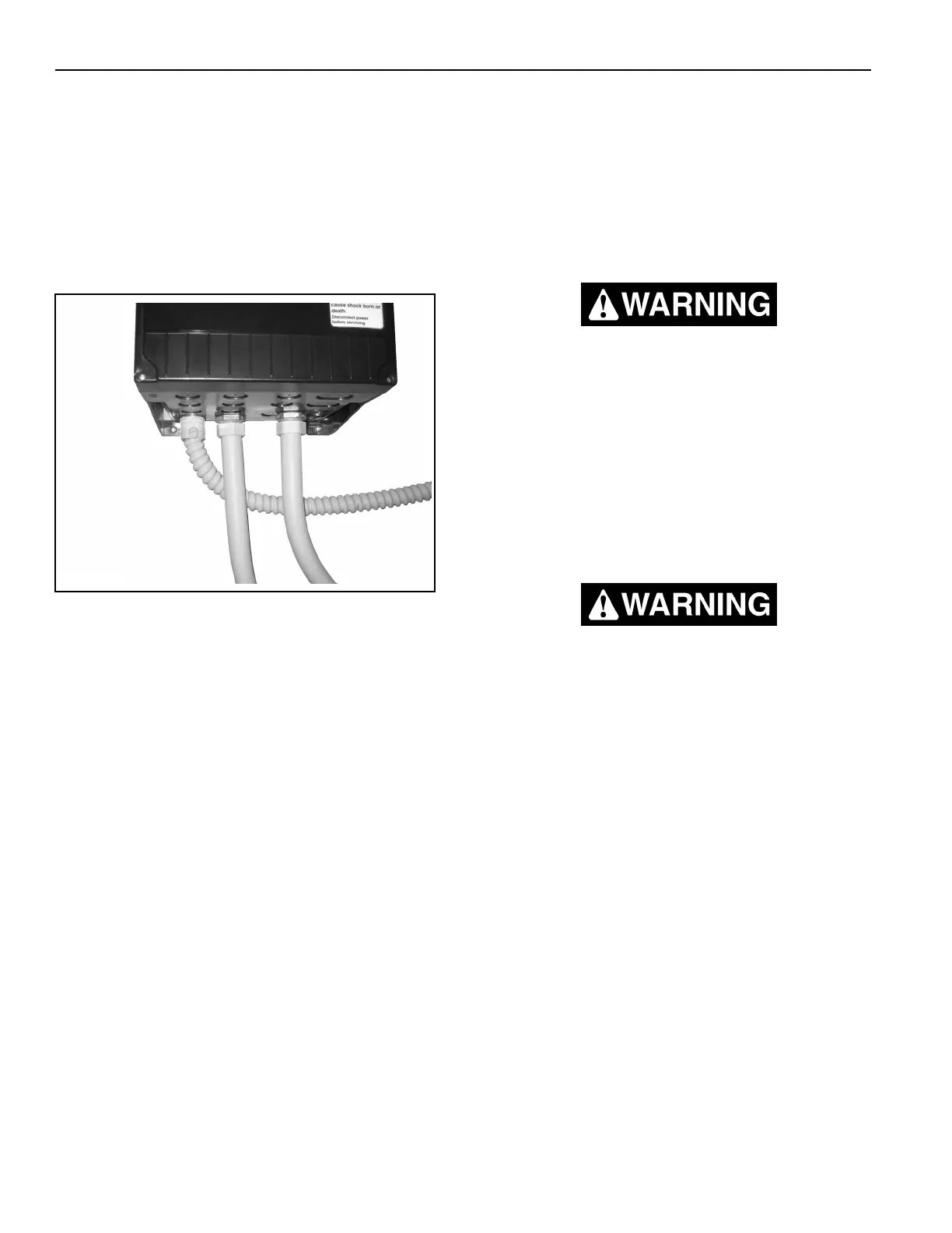
IMPORTANT: The System 4 panel conduit con-
nection locations are NOT knock-
outs. Do NOT use impact to
remove the conduit connection
bosses, or damage to the panel
housing can occur. A drill and
suitable drill bit should be used
to remove the plastic for conduit
connection. (See Figure 11.)
Figure 11
IMPORTANT: If your door is to be mounted on
a freezer, mount the control
panel and the fused disconnect
on the warm side of the wall. It
may also be necessary for you to
install more than one fused dis-
connect. To ensure the equip-
ment is de-energized during
maintenance or service, turn off
all disconnects.
IMPORTANT: Protect the components inside
the control panel from metal
chips when installing conduit.
Seal inside the conduit and
panel if the conduit entering the
panel is coming from an area
having a different temperature
(warmer or colder) than the area
where the panel is located.
IMPORTANT: The schematics shown through-
out this manual are for informa-
tion purposes only. Due to
varying requirements of each
customer, a schematic has been
prepared for your particular door
and it must be used for this
installation. That schematic was
shipped inside the control panel.
The disconnect must be in the OFF position
and properly locked and tagged before wir-
ing of the control panel begins.
IMPORTANT: All conduit entering the control
panel must enter from the bot-
tom of the panel — High voltage
from the bottom left and low volt-
age from the bottom right.
Installing conduit through the
top or sides of the control panel
will void the warranty.
High voltage is present inside this control
panel. Do not touch the circuit board, elec-
trical components, or wiring inside this
panel with power applied.
You must wait at least five minutes after
power is turned off before you can begin
work on the control panel or motor con-
nections. The drive control inside the
panel contains high-voltage capacitors
which take time to discharge once power
is turned off.
A5400021