SYSTEM PARAMETERS—SERVICE LEVEL 2 PARAMETERS
37
P. F 0 1 6–250
milliseconds
Timeout for the wireless
(This sets the wireless timeout within the controller)
NOTE: If the mobile unit doesn’t send a message within
the specified time, the wireless edge will be seen
as tripped.
50
P. F 0 5 1–10 Channel group
(The channel group of the wireless connection)
Channel is selectable 1–10 find setting with highest percent-
age during door operation. Use P:910 set to 23 to display per-
centage during door travel. Place P:910 back to 0 when
finished testing wireless signal.
1
P. F 0 7 00000000–
FFFFFFFF
Mobile unit address
(The address on the mobile unit is used to communicate with
the encoder via the antenna in the head assembly. Each
mobile unit has its own address number.)
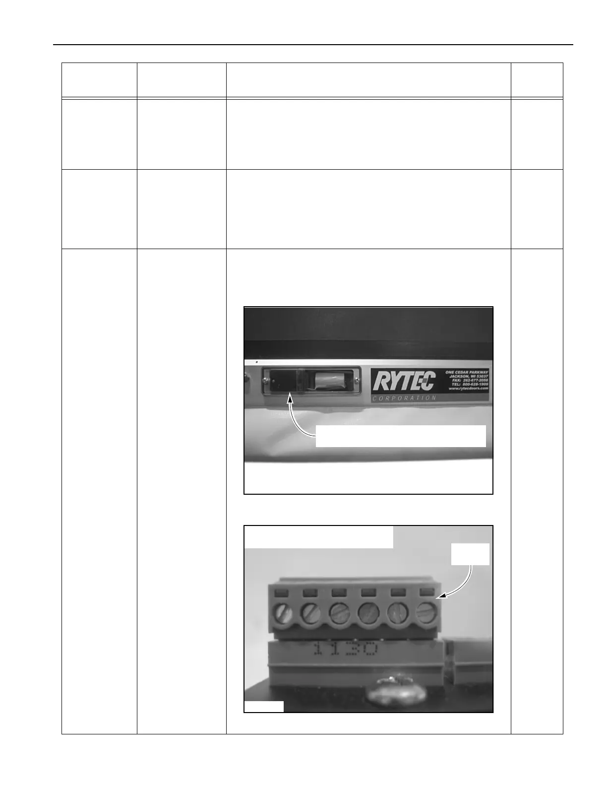
Figure 43
Figure 44
Parameter Range Service Level 2 Parameters
Factory
Setting
A2500246
Mobile Unit Installed in Bottom Bar
Address
A5500025
Mobile
Address
NOTE: The mobile address is shown
mounted on the mobile unit.