3.8
9. Wire each successive pump to zone pumps as needed. Each ground terminal can support
2 ground wires for convenience.
10. 120 VAC power output is also available for a primary pump depending on the hydronic
circuit design.
11. Terminals “XX” are closed any time there is a thermostat call to the wiring center. These
may be wired directly to the thermostat connection on the boiler “TT”. Note, that if an
AX10RF Receiver (sold separately) is used and congured as RX1, the “XX” terminals aren’t
used.
12. The terminals labeled “Zone 1 E/S” are powered any time the
Zone 1 thermostat is closed, and the “PRIORITY” dip switch
is in the “ON” position. These terminals are to be wired to
the DHW demand input of the boiler to change the target
temperature. Under these conditions, none of the other
pumps will operate.
13. Reattach the control cover securing it with the 4 screws
and switch on 120 VAC power to the unit. The LED labeled
“POWER” will be illuminated.
Section 3
Device Installation
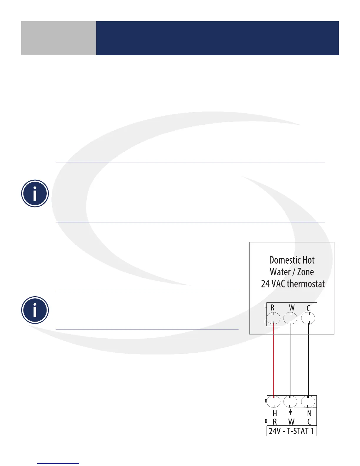
If the priority zone is used on the AKL04/06PRF Wiring Center with a
wired room thermostat that requires separate C terminal, it should
be wired as shown in the drawing. For a DHW thermal switch, a
contact closure across R & W will initiate a demand.
Thermostat Connection
Priority Zone Function (Master wiring center only) – When the “PRIORITY” dip switch is set to the “ON”
position the following occurs:
- Zone 1 pump is turned ON and all other pumps, including those on SLAVE wiring centers, are turned OFF
- If the Zone 1 demand continues for more than 1 hour, the control will override Zone 1 priority and
allow the other zone pumps to operate when a heat demand is present
- Once the Zone 1 demand is satised, the priority override feature resets and a Zone 1 heat demand
will, again, take priority over the other zones.