3.11
Section 3
Device Installation
AX10RF Receiver Installation
The AX10RF Receiver can be congured as a system remote boiler switch (RX1) or a single channel
output to a thermal actuator or zone valve.
1. Carefully read these instructions and all
instructions supplied with the unit before
starting the installation.
2. Inspect the control for damage and be sure all
required parts are included before beginning.
3. Remove the cover by loosening the 2 screws on
the bottom of the unit and rotating the bottom
upward until the top clips disengage.
4. Attach the AX10RF Receiver to the wall in the
desired suitable location.
The AX10RF Receiver must be installed by a qualied contractor. Installation and repairs are to be
performed according to all national and local codes required by the authority having jurisdiction. In the
absence of local requirements, follow ANSI/NFPA 70, National Electrical Code. Failure to follow these
requirements may lead to severe personal injury, death or major property damage. DO NOT SERVICE
this equipment without disconnecting the AC electrical power.
DO NOT INSTALL this control in an area where water
leaks or spray are possible. Failure to comply may
result in serious injury, death or major property
damage due to electrocution or re.
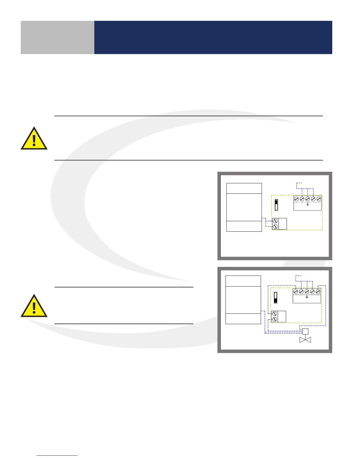
5. Slide the conguration switch on the back of
the cover to the desired position:
• RX1 for system remote boiler switch
• RX2 for valve actuator output
6. Wire the receiver using the appropriate schematic diagram.
7. Re-attach the cover by engaging the cover clips with the
top of the unit and rotating downward until it closes.
8. Fasten the screws at the bottom of the unit.
CH DEMAND
BOILER
H
COM
NO
H NN
RX1
RX2
AX10RF
RECEIVER
24 VAC SUPPLY
H
COM
NO
H NN
RX1
RX2
AX10RF
RECEIVER
24 VAC SUPPLY
CH DEMAND
BOILER
Z
ZONE
VALVE
THIS DOCUMENT CONTAINS
INFORMATION PROPRIETARY
TO AZ ENGINEERING.
DISCLOSURE OF ANY
INFORMATION CONVEYED OR
IMPLIED BY THIS DOCUMENT
WITHOUT EXPRESS WRITTEN
CONSENT BY AZ
ENGINEERING IS FORBIDDEN.
APPROVED BY
DATE
AZ ENGINEERING LLC
AX10RF WIRING SCHEMATIC
SCALE: DRAWING NO: REVISION:
SHEET 1 OF 1
DATE:DRAWN BY:
CN:
RX1 & RX2 CONFIGURATIONS
SCI-180823-01 00
NONE
--
SCEARCE 2018-08-23
REVISION
BY:
0
_ _
DATE:
__/__/__
___ _
NOTES:
1) .
2) .
3) .
KEY:
WATER
ELECTRICAL
CONTROL BOUNDARY
ZONE VALVE
Z
AX10RF WIRING SCHEMATIC
RX2 CONFIGURATION FOR ZONE VALVE
AX10RF WIRING SCHEMATIC
RX1 CONFIGURATION FOR BOILER SWITCH
CH DEMAND
BOILER
H
COM
NO
H NN
RX1
RX2
AX10RF
RECEIVER
24 VAC SUPPLY
H
COM
NO
H NN
RX1
RX2
AX10RF
RECEIVER
24 VAC SUPPLY
CH DEMAND
BOILER
Z
ZONE
VALVE
THIS DOCUMENT CONTAINS
INFORMATION PROPRIETARY
TO AZ ENGINEERING.
DISCLOSURE OF ANY
INFORMATION CONVEYED OR
IMPLIED BY THIS DOCUMENT
WITHOUT EXPRESS WRITTEN
CONSENT BY AZ
ENGINEERING IS FORBIDDEN.
APPROVED BY
DATE
AZ ENGINEERING LLC
AX10RF WIRING SCHEMATIC
SCALE: DRAWING NO: REVISION:
SHEET 1 OF 1
DATE:DRAWN BY:
CN:
RX1 & RX2 CONFIGURATIONS
SCI-180823-01 00
NONE
--
SCEARCE 2018-08-23
REVISION
BY:
0
_ _
DATE:
__/__/__
___ _
NOTES:
1) .
2) .
3) .
KEY:
WATER
ELECTRICAL
CONTROL BOUNDARY
ZONE VALVE
Z
AX10RF WIRING SCHEMATIC
RX2 CONFIGURATION FOR ZONE VALVE
AX10RF WIRING SCHEMATIC
RX1 CONFIGURATION FOR BOILER SWITCH