5.2
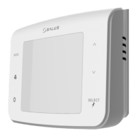
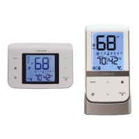
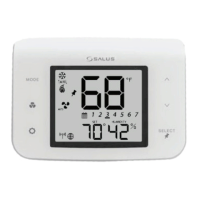
AS20WRF/BRF Thermostat with AKL01/04/06PRF or
AKL08RF Wiring Center
To begin pairing, all of the required
components are to be powered: AS20WRF/
BRF Thermostat, AKL Wiring Center and
AX10RF Receiver congured RX1 for boiler
demand (optional). The Network Status LED
on the AKL Wiring Center should be ashing
and, if the AX10 RF Receiver is used, the red
backlight behind the Auto/Manual switch
should also be ashing.
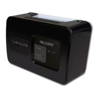
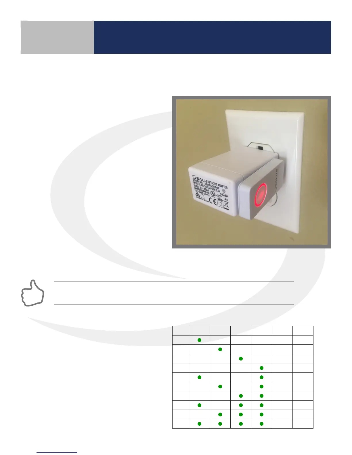
1. Press and hold the lighted red button on
the AC10RF Coordinator for 5 seconds,
until the LED begins ashing, to begin
pairing. When the network status LED on
the AKL Wiring Center and the backlight
on the Auto/Manual button of the AX10RF
Receiver (if used) stop ashing, they have
been paired and you are ready to pair the
AS20WRF/BRF Thermostat.
Section 5
Device Pairing & Setup without Internet
If the network status LED on the AKL Wiring Center continues blinking, turn o the power to
the device for 10 seconds.
2. Once the network status LED on the
AKL Wiring Center is no longer ashing,
press the pairing button on the AC10RF
Coordinator for two seconds. Zone LED
on the Wiring Center will illuminate the ID
number of the device (see ID# key below)
ID # Zone 1 Zone 2 Zone 3 Zone 4 Zone 5 Zone 6
1
2
3
4
5
6
7
8
9
0
AKL Wiring Center ID Number Key