5.7
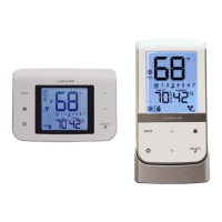
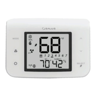
AS20WRF/BRF Thermostat with AX10RF Receiver
for Boiler Switching (RX1)
Be sure the switch on the inside cover of the AX10RF Receiver has been congured to RX1, for
boiler demand switching, and the Receiver has been wired as indicated in Section 3, Installation.
To begin pairing, all of the required components are to be powered: AS20WRF/BRF Thermostat
and AX10RF Receiver. The lighted LED button on the AC10RF Coordinator should be solid red.
The switches on the cover of the Receiver should be in Auto and On positions respectively.
Pairing the AX10RF in the RX1 conguration with an AS20WRF/BRF is only required
when used in a 1 to 1 relationship without an AKL Wiring Center or other system device.
Each system will only support one AX10RF congured as RX1 and one congured as RX2.
1. Press and hold the lighted red button on the AC10RF Coordinator for 5 seconds, until the LED
begins ashing, to begin pairing.
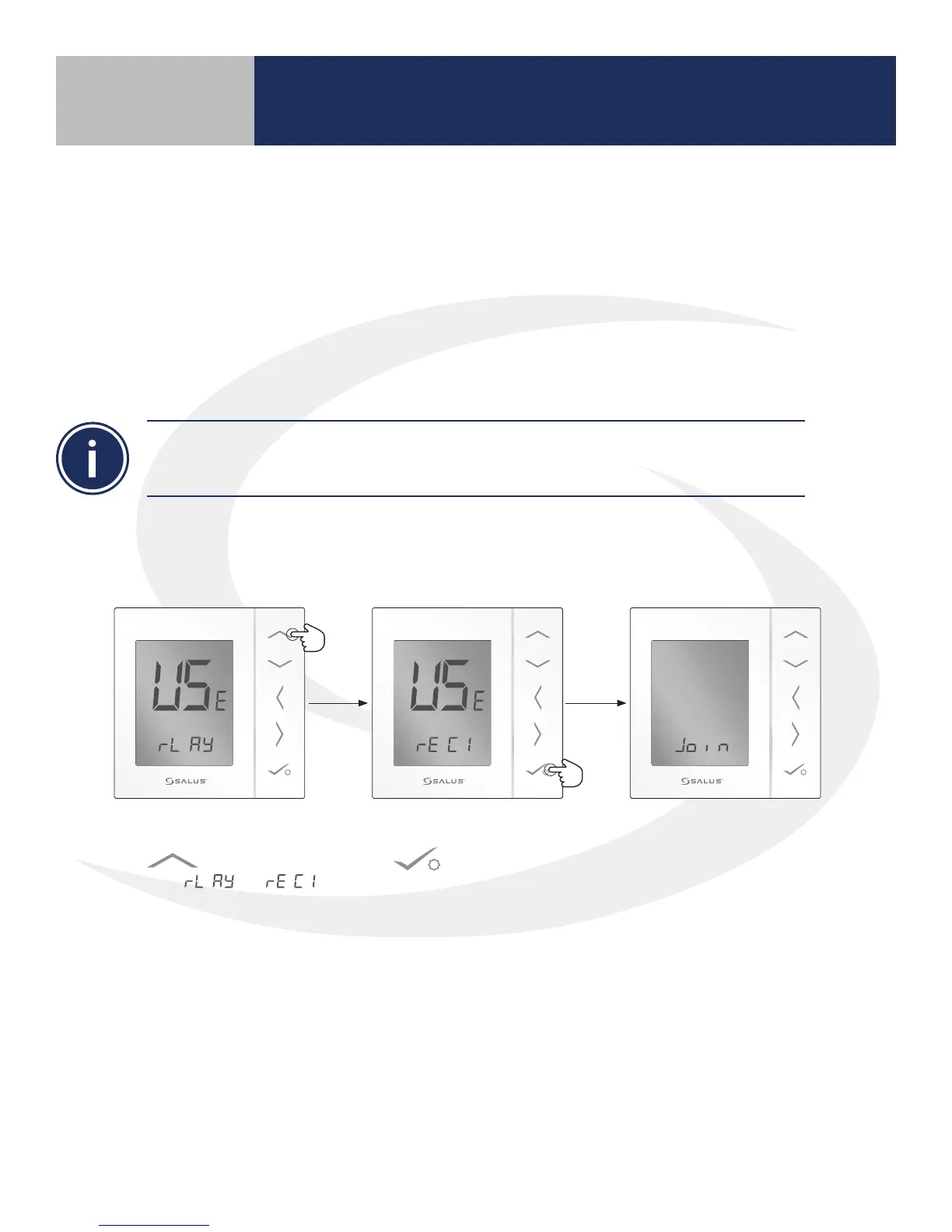
2. Use the Up arrow
to change to
from to .
3. Then press conrm
.
The AS20WRF/BRF
Thermostat will join the
wireless network and begin
the pairing sequence.
Section 5
Device Pairing & Setup without Internet