5.6
9. Once all Actuators have
been scanned, press
on the AS20WRF/
BRF Thermostat to pair the
valves with the Thermostat.
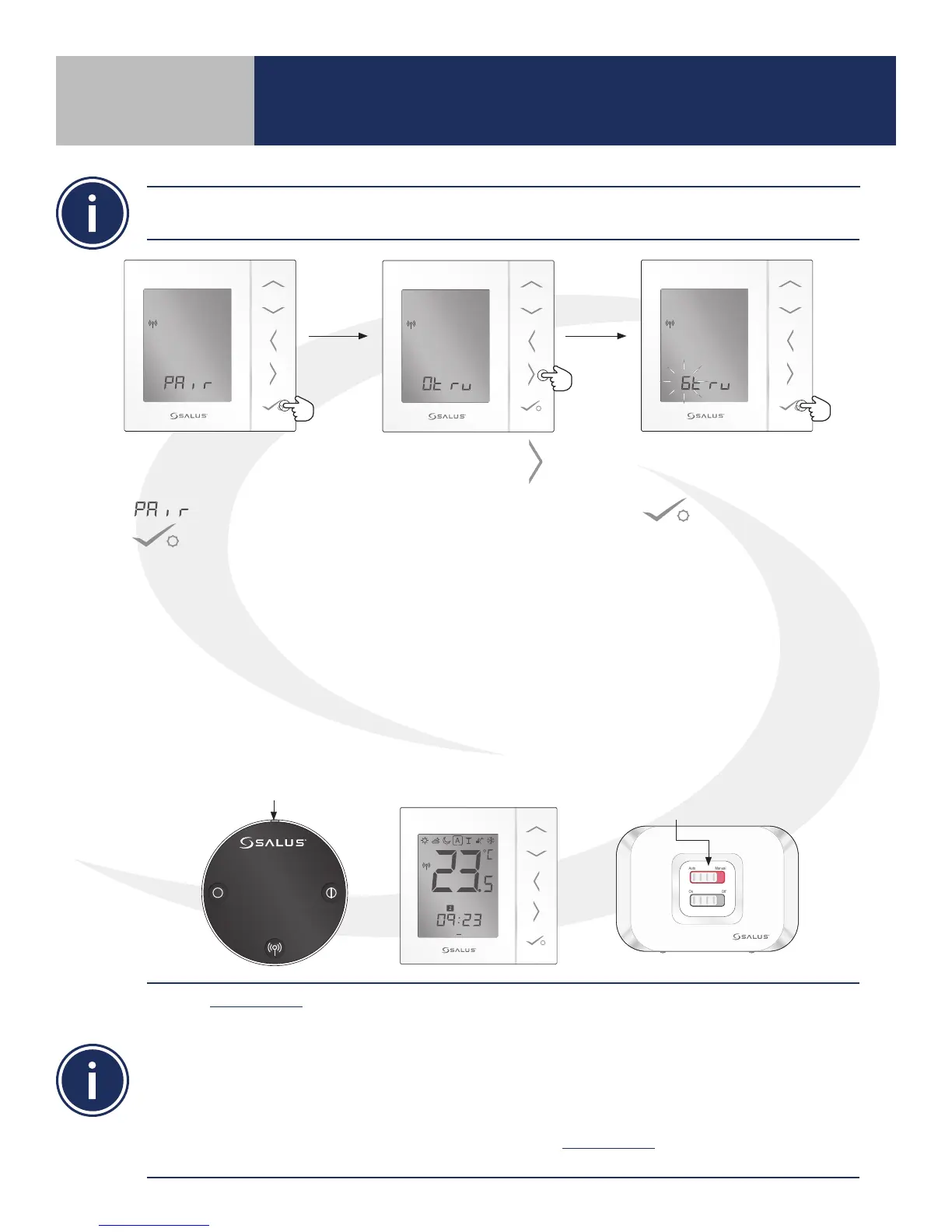
7. When the AS20WRF/BRF
Thermostat displays
, press conrm
.
8. Press right arrow
to begin scanning for
ARV10RFM Actuators that
are in the pairing mode.
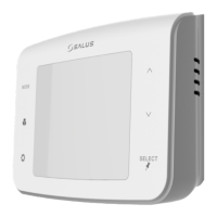
10. When all Thermostatic Regulator Valves (TRV) have been set up, press & hold the pairing button
on the AC10RF Coordinator or the multi button on the SG888ZB Gateway to complete pairing.
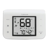
When the AS20WRF/BRF Thermostat is successfully paired, the screen will display the current
temperature, the LED indicator on the ARV10RFM Radiator Valve Actuator turn o and, if applicable,
the LED back light on the AX10RF Receiver’s Auto/Manual switch will appear solid red. The LED on the
AC10RF Coordinator will be solid red. If the SG888ZB Gateway is used without an internet connection,
the LED ring on the multi button will be solid red.
Use the Identify Mode to check system communication and conguration.
1) Press and release the AC10RF Coordinator button to enter Identify Mode. The light will ash green.
Each item connected will give an indication that it is connected.
a. AKL-RF Wiring Center – G1 & G2 ash red
b. AX10RF Receiver – On/O Switch backlight ashes green
c. AS20WRF/BRF Thermostat – Displays a 10 minute countdown with the letters “id” below it
until identify times out.
2) Press and release the AC10RF Coordinator button to exit Identify Mode. The light will change to solid
red indicating that the network is active
Each AS20WRF/BRF Thermostat is capable of controlling up to 6 ARV10RFM Actuators. All Actuators
intended for pairing with a single thermostat are to be in pairing mode before proceeding
LED is solid red.
1 2 3 4 5 6 7
PM
Auto Manual
On Off
LED is o.
Section 5
Device Pairing & Setup without Internet