2.5 EarthingConceptandPowerSupply
There is a shielding and earthing plate in the lower part of the PCD1 housing.
This combines with the shielding and earthing plate in the module holder to form
a common, wide-area earthing point for all I/O modules and the external power
supply.
If an I/O module is inserted in the module holder, the metal claws of the shielding
plate in the PCD1 housing form a reliable, multiple contact point with the module.
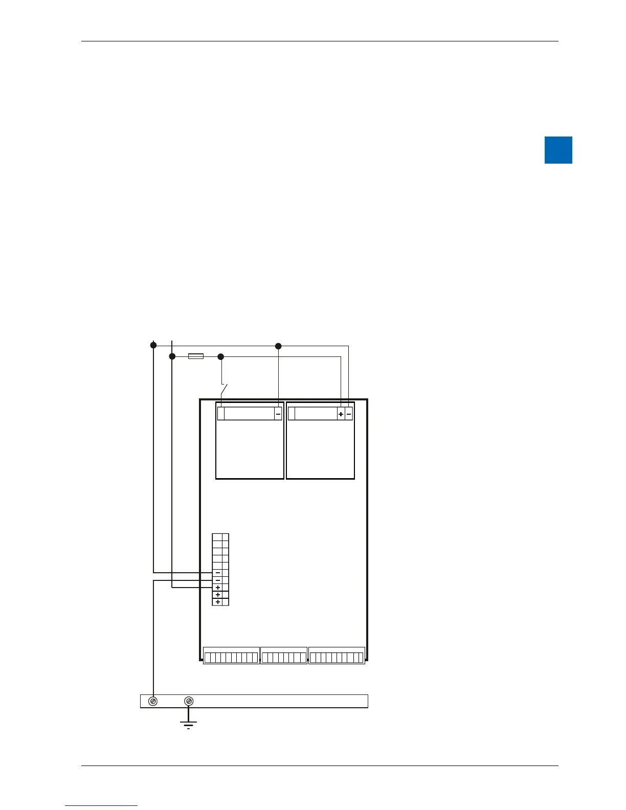
The zero potential (minus) of the 24 VDC supply is connected to the minus
terminal of the supply. This should be connected to the earthing rail using
the shortest possible cable (< 25cm) with a cross-section of 1.5 mm
2
.
Any shielding of analogue signals or communications cables should take place
either through a minus terminal or through the earthing rail to the same earth
potential. All minus connections are linked internally. For problem-free operation,
these connections should be externally reinforced with short cables with a cross-
section of 1.5 mm
2
.