4V
3V
2V
1V
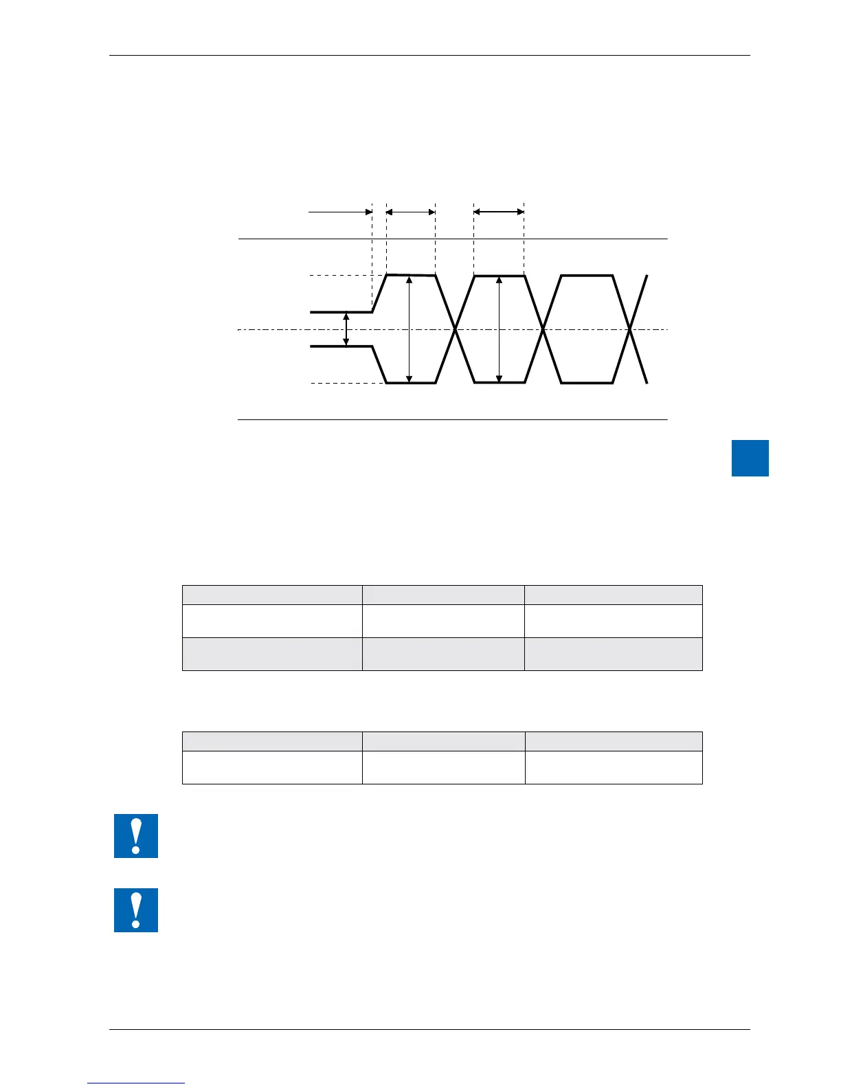
VOH
VOL
VOZ
/TX
TX
VOZ = 0.9Vmin…1,7V
VOH = 2 V min (with load) … 5 V max (without load)
VOL = -2 V … -5 V
The RS-422 is in idle status in the position “mark”
RS-422:
Signaltype Logicstatus Polarity
Data signal 0 (empty)
1(character)
TX positive to /TX/TX positive
to TX
Control/message signal 0(o)
1 (on)
/RTS positive to RTSRTS
positive to /RTS
RS-485:
Signaltype Logicstatus Polarity
Data signal 0 (empty)
1(character)
RX-TX positive to /RX-/TX/RX-/
TX positive to RX-TX
Notallmanufacturersusethesameconnectionconguration.Therefore,itmaybenecessary
to cross the data lines.
In order to ensure fault-free operation of an RS-485 network, the network should be closed
at both ends. Cables and terminators should be selected according to Manual 26-740 “Installation
Components for RS-485 Networks”.