Hardware Manual PCD1.M2110R1 │ Document 27-619 │ Version ENG 04 │ 2018-08-20
Saia-Burgess Controls AG Communications Interfaces
6
6-4
On-board│Port#0RS-485
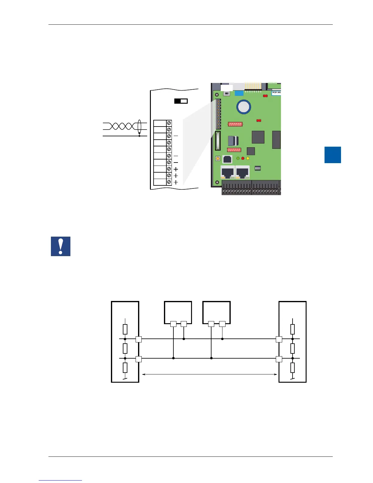
6.1.3 Port#0(RS-485,notelectricallyisolated)
In S-Bus, Modbus or MC4 communications mode, an RS-485 link can be
established via port 0 with terminal block X3, terminals 38 and 39
39 D
/D
WD
WD
RX - TX
/RX - /TX
S1
38
37
36
35
34
33
32
31
30
RS-485
Bus cable
X3
O
C
X3
S1
SwitchS1,connectingordisconnectingtheRS-485terminationresistors
WithswitchS1,theterminatingresistorsareswitchedonoro.SwitchS1must
be set to “C” (closed) at both outer stations. For all other stations switch S1
remains in the position “O” (factory setting).
SchematicdiagramofanRS-485buswithterminatingresistors.
+5 V
/RX - /TX
n n
39 n
/n
/n/n
38
RX - TX
+5 V
Pull up
330 Ohm
Termination
Resistor
150 Ohm
Segment length max. 1200 m
max. 32 stations
Bus RS-485
First station Middle stations End station
Pull down
330 Ohm
For more details see in the Manual 26-740, Installation components for RS-485
Networks.