4.1.6 InterruptInputs(TerminalBlockX1)
Basic principle
Duetotheinputlterandtheeectofthecycletime,thedigitalinputmodulesare
not suitable for reacting immediately to events or fast computing processes. Some
CPUs have interrupt inputs for this purpose.
Ifapositiveankisdetectedataninterruptinput,thecorrespondingXOB(e.g.
XOB20)willbecalled.ThecodeinthisXOBdeneshowtheunitshouldreactto
the event, e.g. increment a counter.
The code in XOBs, which is called by interrupt inputs, must be as short
aspossiblesothatsucienttimeremainsbetweentheinterruptsinorder
to process the rest of the user program.
Many FBoxes are intended for cyclical calling and are not suitable for use
in XOBs, or are only suitable to a limited extent. Exception: The FBoxes
of the Graftec family (standard library) are well-suited.
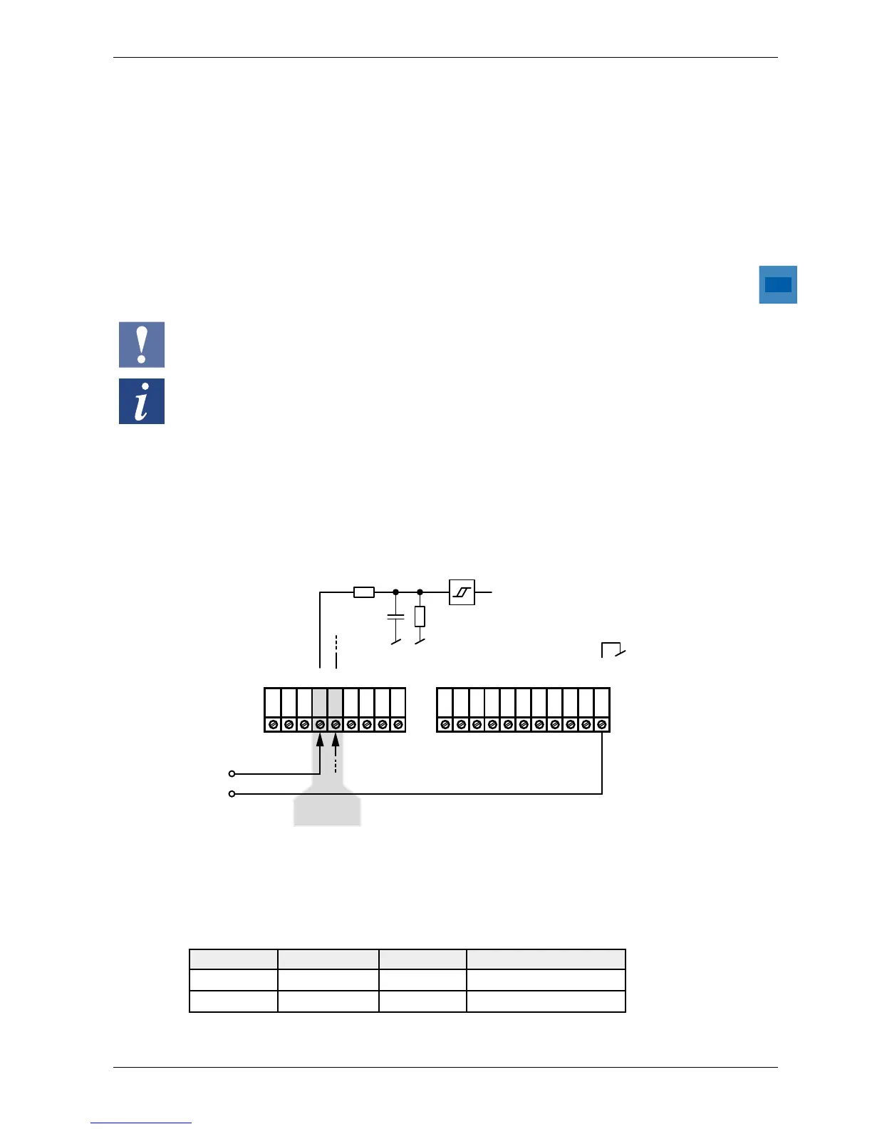
PCD1 Interrupt Inputs 24 VDC
Both two interrupt inputs are located on the main circuit board and can
beconnectedthroughthe9-pinplug-inTerminalBlockX1(Terminals15
and16).Sourceoperationisalwaysused.
Int1
11
12
13
14
15
16
17
18
19
10
9
8
7
6
5
4
3
2
1
0
I2
I3
I1
I0
O0
O2
O3
O1
IO5
IO4
IO6
IO7
X0X1
U ext.
GND
IX0
IX1
AI0
AI1
-
+
-
24 V
CC
0 V
CC
Input signals (always source operation): H = 15...30 V
L = - 30...+ 5 V or unconnected
interrupt
inputs
Interruptassignment
Terminal Caption Interrupt Called XOB
15 IX0 Int0 XOB 20
16 IX1 Int1 XOB 21