1 Graphical overview
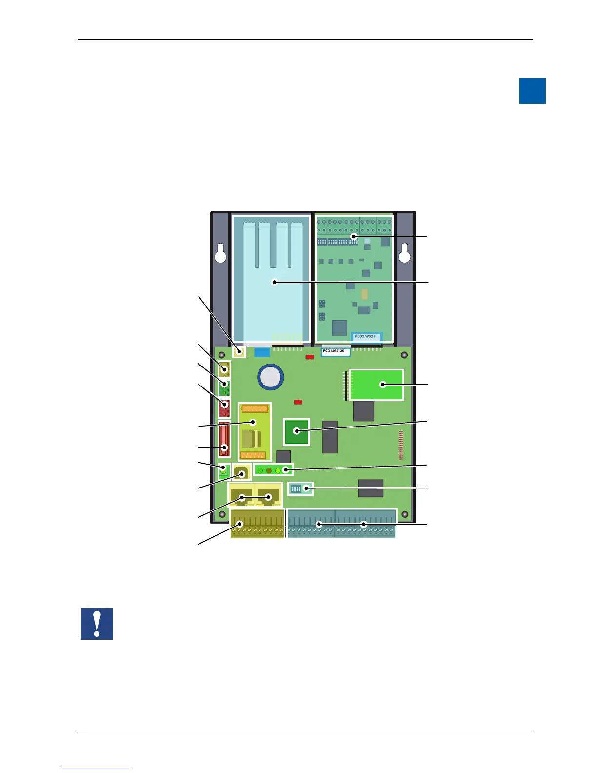
The graphical overview shows some of the most important items for the operating
manual of the PCD1.M2110R1 (PCD1.Room).
By clicking on the highlighted components and/or connections, you can jump
directly to the corresponding section in the document.
The numbers separated by dots correspond to the chapters.
Slot IO1 is only for operation with a PCD2.W525 module. This module is factory
installed and included with delivery.
If this module is removed, the PCD1.Room cannot switch into RUN mode
M1
SlotA
Slot for memory
module
3.7
COSinus Operating
system and
automation server
3.4
Terminals for
integrated inputs
and outputs
4.1.1
Terminating
resistance (RS-485)
6.1.3
Battery 2.4
Slot, optional serial
interface for commu
nication 6.1.4 or
Supply voltage 2.5
Watch Dog 3.8
On-board RS-485
interface 6.1.3
USB/PGU
connection 6.1.1
RUN/STOP button
3.6.1
Slot A connection
terminal 6.1.4
Ethernet connection
(2 port switch) 6.1.2
Operation LEDs
3.6
IO-modules 4.3
Free Slot with SPI
(faster seriel Bus) for
IO- or Communica-
tionsmodules
4.2
Integrated
IO analogmodul
PCD2.W525 4.1.7
Selection of the
analog input range
4.1.2