2.3 HandlingI/Omodules
The power supply must be disconnected before a module is inserted or removed!
This also applies if changes are made on the module (such as insertion/removal
of jumpers).
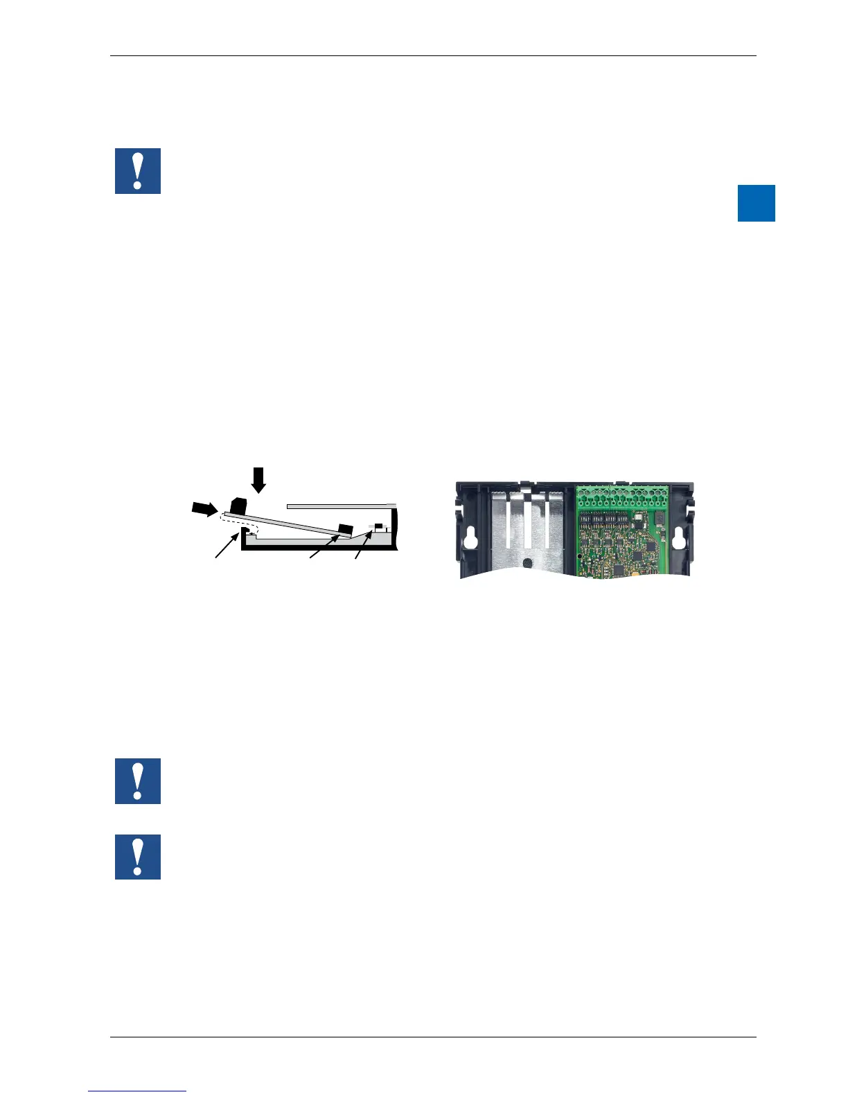
Insertingthemodule
Metal plates can be seen on the base of the housing. They provide shielding and
are each precisely aligned to the module slot.
An I/O module can be inserted into slot IO0:
1. Thisisdonebycarefullyinsertingthemodule,socketconnectorrst(usually
blue), and pushing it gently toward the system bus plug until the stop. Guides
assist this process.
2. Assoonastheoppositeendofthemoduleisushwiththeretaininglatch
of the housing base, press the module down toward the plate.
2
1
retaining latch
jack plug
system bus-
plug
Slot 0
Slot 1
Removingthemodule
With your thumb, push the retaining latch no more than 1 mm away from
the module (from the I/O/ connection plug and/or terminal), pressing outward. .
With your other hand, lift the module at the I/O connection plug just above the
retaining latch and withdraw the module from the slot.
Slot 1 is only for operation with a PCD2.W525 module. This module is factory
installed and included with delivery.
If this module is removed, the PCD1.Room cannot switch into RUN mode.
Be careful not to bend the metal claws of the shielding plate inward with a tool (in
other words, never use a screwdriver to pry the module out). This could result in a
short-circuit, with consequent damage to the module and/or controller.