Operating instructions for actuators type AB with SMARTCON control unit
OM-ENGLISH-CSC-V2.08-2019.11.07 4 Installation Instructions
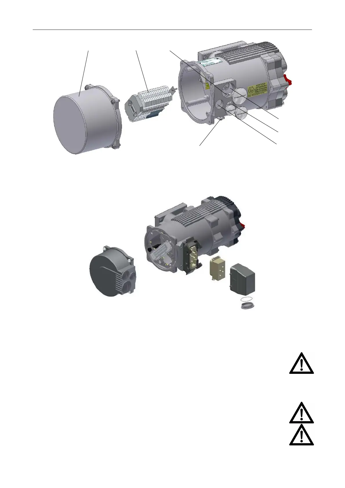
Figure 12: 1. . . connection plug housing, 2. . . terminal strip, 3. . . inside ground connection, 4. . . metallic ca-
ble glands (closed with blind screw connections at delivery) M40x1,5, 5. . . M32x1,5, 6. . . M25x1,5,
7. . . outside ground connection
Figure 13: size 2 with the additional plug
3 phase power is applied in positive turning direction of the electric field on the connectors L1, L2, L3 according
the wiring diagram.
Before starting the actuator the turning direction of the electronic field should be checked.
NOTE: If phase sequence of the three phase power supply system is wrong the integrated
phase sequence monitoring generates an error and the actuator is blocked. (see section 7.1,
page 24)
If you need a reverse rotation of the actuator (ccw) you must change this in the control unit (section 7.1,
page 24).
Please also note the information about the installation of an external motor protection circuit breaker
- see section 2.7.2, page 7.
If, during outdoor installation, commissioning is not carried out immediately after electrical connec-
tion, the power supply must be connected at a minimum to achieve a heating effect. In this case,
the silica gel may remain in the connection compartment until commissioning.
CAUTION: see section 3.3, page 9
11
 Loading...