8 Status area
Operating instructions for actuators type AB with SMARTCON control unit
OM-ENGLISH-CSC-V2.08-2019.11.07
8 Status area
The status area presents current process and diagnostic data. There data is read-only. To access the status
area, move the control switch in the direction where the selector switch should be in the neutral position or in
the remote position.
The status area is divided into 2 sub-areas:
• Status
• History
8.1 Status
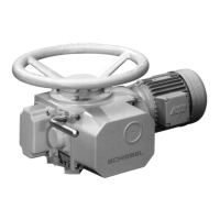
8.1.1 Status – Bin. Outputs
Display of binary outputs: The display shows output control as opposed to output status, i.e. the supply of the
binary outputs is ignored. A switched output is represented by 1.
Figure 66: 1. . . Output Number, 2. . . Signal (0 = LOW; 1 = HIGH
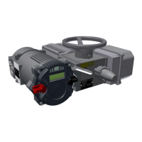
8.1.2 Status – Bin. Inputs
Display of binary inputs: A set input is represented by 1.
Figure 67: 1. . . Input number, 2. . . Signal (0 = LOW; 1 = HIGH)
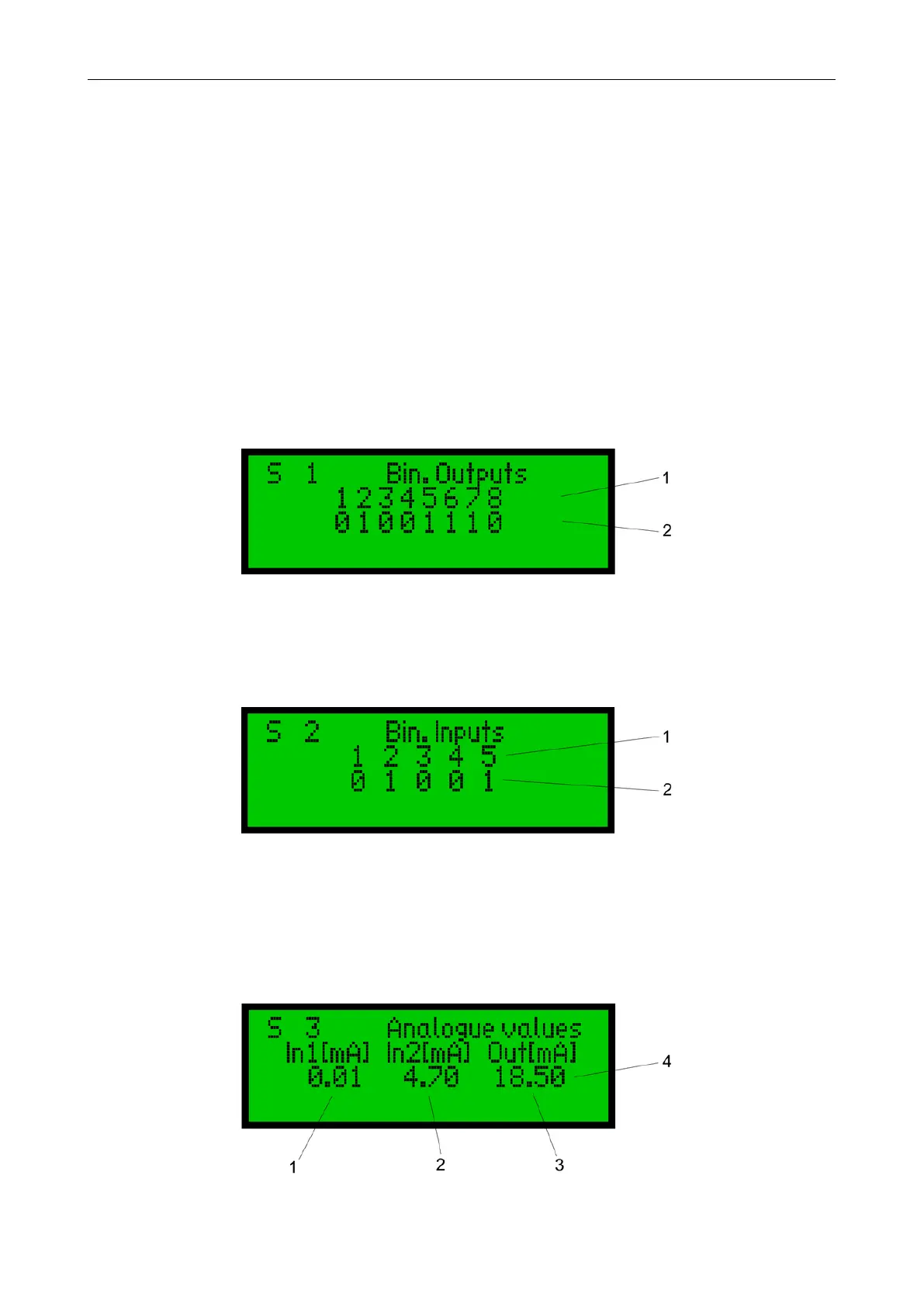
8.1.3 Status – Analogue values
Display of analogue values: Input 1 (In1) is used by the positioner as the setpoint; Input 2 (In2) serves as an
external value for the optional PID controler. In the analogue output (out), only the control signal is shown,
regardless of whether the output current actually flows or not (interruption of the current loop).
Figure 68: 1. . . Input 1, 2. . . Input 2, 3. . . Output, 4. . . all values in mA
42
 Loading...